
Concept explainers
Videos
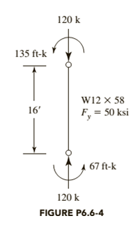
The member shown in Figure P6.6-4 is part of a braced frame. The load and moments are computed from service loads, and bending is about the
a. Use LRFD.
b. Use ASD.

Trending nowThis is a popular solution!

Chapter 6 Solutions
Steel Design (Activate Learning with these NEW titles from Engineering!)


- A fully embeded precast, prestressed concrete pile is 12 m long and is driven into homogeneous layer of sand. The pile is square in cross section, with sides measuring 305 mm. The dry unit weight of sand is 16.8 kN/m, and the average effective soil friction angle is 35°. The allowable working load is 338 kN. If 240 kN is contributed by the frictional resistance and 98 kN is from the point load, determine the elastic settlement of the pile. Use Ep 21 x 10 kN/m², E, 30000 kN/m², and μ-0.3.arrow_forwardA 15 in. x 26 in. rectangular RC beam (shown in figure below) supports a service uniform deadload of 1.3 kip/ft and a service uniform live load of 1.6 kip/ft. The dead load includes the beam’sself-weight. Design the reinforcement required for maximum moments and show the design insketches. Use f c ’ = 4,000 psi and f y = 60,000 psi. The beam is used in an open parking garage andis exposed to weather.a. Find factored maximum bending moments.b. Design for max. negative moment.c. Design for max. positive moment.Hint: Assume an initial beam shape (b, d), then solve for the needed reinforcements at the maximumnegative and positive factored bending momearrow_forwardA structure is an intersecting hip roof with the main hip roof outside dimensions being 73 ft long and the width being 30 ft wide. The intersection portion extends 20 ft beyond the 30-ft side, and the intersecting portion is 20 ft wide. The overhang is 2 ft 6 in. and the slope is 5:12. The rafters are 16 in. on center. Based on the information provided, what is the total length of the common rafters in linear feet?arrow_forward
- How many board feet is 200 lnft of 2 in. × 6 in wood studs.arrow_forwardExample: Determine the minimum slope in the upper reach of a chute section of 30 m width. The range of discharge is 150 to 2000 m³/sec. n = 0.015.arrow_forward1. Zinc is an important trace nutrient for photosynthetic organisms (e.g., phytoplankton) in sea water. Calculate the speciation of zinc (Zn(II)) in seawater assuming Zn(II) TOT = 5 x 10⁻⁸ M. Provide a list of the metal-ligand complexes and their corresponding stability Constants that you will include in your calculation. If you decide to exclude any of the complexes for which stability constants are provided in Table 9.4, please list these separately and explain your rationale. b. Compute the concentrations of the metal-ligand complexes identified in part a. c. Compute the activities of the metal-ligand complexes using the concentrations calculated in part b and using the data in Table 9.6B to calculate the activity coefficients. (Note—you likely already have a spreadsheet where you calculated activity coefficients from week 3!)arrow_forward
- Q.2 The required design span for the beam given in Q.1 is increased to 18 ft. The design loads are the same as given in Q.1 Check the adequacy of a 10"x16" 10 Caribbean Pitch Pine – (Select Structural) for this these design conditions.arrow_forwardThe timber floor framing for a building comprise floor joists using 2" wide nominal lumber is to be constructed as shown in Fig. 1. The Dead load (D) = 26 lbs./ft² (inclusive of joists and flooring) and the live load L= 40 lbs./ft². Lateral torsional buckling is prevented for all members and normal service conditions and temperatures are expected. (i) Design the floor joists using 2" wide nominal lumber using Southern Pine No. 1 (ii) Design the floor beams using Caribbean Pitch Pine (Select Structural). (Assume a 8" x 14” trial section to estimate beam self-weight for your initial design). Density of Caribbean Pitch Pine = 50 lbs/ft³ (800 kN/m³).arrow_forwardP12.38 WP At a point on the free surface of a stressed body, a normal stress of 64 MPa (C) and an unknown positive shear stress exist on a horizontal plane. One principal stress at the point is 8 MPa (C). The absolute maximum shear stress at the point has a magnitude of 95 MPa. Determine the unknown stresses on the horizontal and vertical planes and the unknown principal stress at the point.arrow_forward
- A pile group of 25 piles has to be proportioned in a uniform pattern in soft clay with equal spacing in all directions. Assuming the value of cu to be constant throughout the depth of the piles, determine the optimum value of spacing of piles in the group. Assume a = 0.7. Neglect point bearing effect, and assume the piles to be circular.arrow_forwardExample 5 By using the yield line theory, determine the moment (m) for an isotropic reinforced concrete two-way slab (supports on two S.S sides shown in figure under the load (P) (all dimensions are in mm). Solve by using equilibrium method m m 3000 2000 2000arrow_forwardA +7.5% grade meets a horizontal grade on a section of a rural mountainous highway. If the length of the crest vertical curve formed in that section is 300 ft long, determine the safe operating speed on the highway.arrow_forward
 Steel Design (Activate Learning with these NEW ti...Civil EngineeringISBN:9781337094740Author:Segui, William T.Publisher:Cengage Learning
 Materials Science And Engineering PropertiesCivil EngineeringISBN:9781111988609Author:Charles GilmorePublisher:Cengage Learning
 Principles of Foundation Engineering (MindTap Cou...Civil EngineeringISBN:9781305081550Author:Braja M. DasPublisher:Cengage Learning
 Engineering Fundamentals: An Introduction to Engi...Civil EngineeringISBN:9781305084766Author:Saeed MoaveniPublisher:Cengage Learning
 Principles of Foundation Engineering (MindTap Cou...Civil EngineeringISBN:9781337705028Author:Braja M. Das, Nagaratnam SivakuganPublisher:Cengage Learning