
Videos
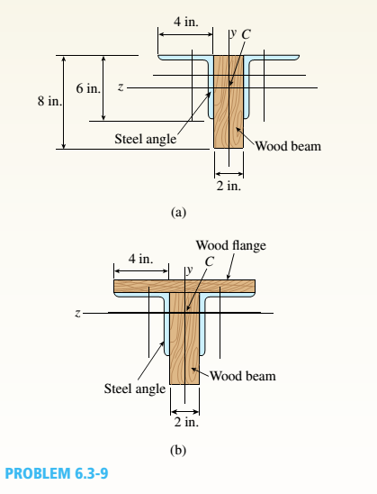
A simple beam thai is IS ft long supports a uni¬form load of intensity a. The beam is constructed of two angle sections, each L (1 × 4 × 1/2, on either side of a 2 in. x 8 in. (actual dimensions! wood beam (see the cross section shown in the figure part a]. The modulus of elasticity of the s I eel is 10 limes that of the wood,
(a) If the allowable stresses in the steel and wood are 12,000 psi and 900 psi. respectively, what is the allow atile load a t. A olc. Disregard the weight of the beam, and see Table F-5(a) of Appendix I ' for I lie dimensions and properties of the angles.
(b) Repeal partial if a I in. 10 in. wood Hange tactual dimensions) is added i see figure pallhi b).
a.
The allowed load
Answer to Problem 6.3.9P
The allowed load
Explanation of Solution
Given:
We have the following data for calculation.
Length of the beam,
Load with intensity of as q
Two angle sections used for construction of the beam,
Allowed stress of steel,
Allowed stress of wood,
Concept Used:
First, Area, centroids and moment of inertia for wood and steel sections is determined.
This step is followed by further calculation involving moment for wood and steel section and maximum moment.
Calculation:
We have
Let us first calculate for wood.
- Centroidal distance,
- Area of the wood beam,
Now, calculation for two sections of steels.
So, further calculating,
Now, performing transformation of moment if inertia below :
We are determining moment for wood.
Moment for steel sections,
Now, the maximum moment would be:
But the equation for maximum moment is:
Conclusion:
The allowed load
b.
The allowed load
Answer to Problem 6.3.9P
The allowed load
Explanation of Solution
Given:
We have the following data for calculation.
Length of the beam,
Load with intensity of as q
Two angle sections used for construction of the beam,
Allowed stress of steel,
Allowed stress of wood,
Concept Used:
First, Area, centroids and moment of inertia for wood and steel sections is determined.
This step is followed by further calculation involving moment for wood and steel section and maximum moment.
Calculation:
So, the width and height of flange would be,
Now for transformed sections,
Now performing transformation of moment if inertia as below,
We are determining moment for wood.
Moment for steel sections,
Now, the maximum moment would be,
But, the equation for maximum moment is:
Conclusion:
The allowed load is calculated by the moment equations and given information.
Want to see more full solutions like this?
Chapter 6 Solutions
Mechanics of Materials, SI Edition


- (Read Image)arrow_forwardM16x2 grade 8.8 bolts No. 25 C1- Q.2. The figure is a cross section of a grade 25 cast-iron pressure vessel. A total of N, M16x2.0 grade 8.8 bolts are to be used to resist a separating force of 160 kN. (a) Determine ks, km, and C. (b) Find the number of bolts required for a load factor of 2 where the bolts may be reused when the joint 19 mm is taken apart. (c) with the number of bolts obtained in (b), determine the realized load factor for overload, the yielding factor of safety, and the separation factor of safety. 19 mmarrow_forwardProblem4. The thin uniform disk of mass m = 1-kg and radius R = 0.1m spins about the bent shaft OG with the angular speed w2 = 20 rad/s. At the same time, the shaft rotates about the z-axis with the angular speed 001 = 10 rad/s. The angle between the bent portion of the shaft and the z-axis is ẞ = 35°. The mass of the shaft is negligible compared to the mass of the disk. a. Find the angular momentum of the disk with respect to point G, based on the axis orientation as shown. Include an MVD in your solution. b. Find the angular momentum of the disk with respect to point O, based on the axis orientation as shown. (Note: O is NOT the center of fixed-point rotation.) c. Find the kinetic energy of the assembly. z R R 002 2R x Answer: H = -0.046ĵ-0.040 kg-m²/sec Ho=-0.146-0.015 kg-m²/sec T 0.518 N-m =arrow_forward
- Problem 3. The assembly shown consists of a solid sphere of mass m and the uniform slender rod of the same mass, both of which are welded to the shaft. The assembly is rotating with angular velocity w at a particular moment. Find the angular momentum with respect to point O, in terms of the axes shown. Answer: Ñ。 = ½mc²wcosßsinßĵ + (}{mr²w + 2mb²w + ½ mc²wcos²ß) k 3 m r b 2 C لا marrow_forwardOnly question 2arrow_forwardOnly question 1arrow_forward
- Only question 3arrow_forwardI have Euler parameters that describe the orientation of N relative to Q, e = -0.7071*n3, e4 = 0.7071. I have Euler parameters that describe the orientation of U relative to N, e = -1/sqrt(3)*n1, e4 = sqrt(2/3). After using euler parameter rule of successive rotations, I get euler parameters that describe the orientation of U relative to Q, e = -0.4082*n1 - 0.4082*n2 - 0.5774*n3. I need euler parameters that describe the orientation of U relative to Q in vector basis of q instead of n. How do I get that?arrow_forwardDescribe at least 4 processes in engineering where control charts are (or should be) appliedarrow_forward
- Describe at least two (2) processes where control charts are (or should be) applied.arrow_forwardProblem 3: A cube-shaped spacecraft is in a circular Earth orbit. Let N (n,) be inertial and the spacecraft is denoted S (ŝ₁). The spacecraft is described such that ¯½º = J ŝ₁ŝ₁ + J ŝ₂§₂ + J §¸Ŝ3 Location of the spacecraft in the orbit is determined by the orbit-fixed unit vectors ê, that are oriented by the angle (Qt), where is a constant angular rate. 52 €3 3> 2t 55 Λ Из At the instant when Qt = 90°, the spacecraft S is oriented relative to the orbit such that 8₁ = 0° Space-three 1-2-3 angles 0₂ = 60° and ES = $₂ rad/s 0₁ = 135° (a) At this instant, determine the direction cosine matrix that describes the orientation of the spacecraft with respect to the inertial frame N.arrow_forwardThis problem illustrates that the factor of safety for a machine element depends on the particular point selected for analysis. Here you are to compute factors of safety, based upon the distortion-energy theory, for stress elements at A and B of the member shown in the figure. This bar is made of AISI 1006 cold-drawn steel and is loaded by the forces F = 1.100 kN, P = 8.00 kN, and T = 50.00 N-m. Given: Sy = 280 MPa. B -100 mm- 15-mm D. a) Determine the value of the axial stress at point B. b) Determine the value of the shear stress at point B. c) Determine the value of the Von Mises stress at point B. P Farrow_forward
 Mechanics of Materials (MindTap Course List)Mechanical EngineeringISBN:9781337093347Author:Barry J. Goodno, James M. GerePublisher:Cengage Learning