
Concept explainers
Videos
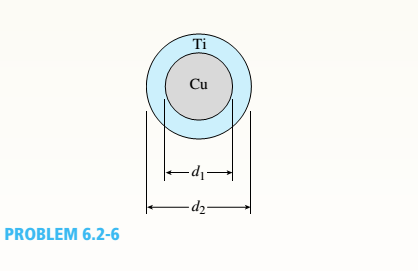
A r o lukI f/frm f «m t ub e of ou t sid e d ia met er ^ and a copper core of diameter dxare bonded to form a composite beam, as shown in the figure,
(a) Derive formulas for the allowable bending moment M that can be carried by the beam based upon an allowable stress <7Ti in the titanium and an allowable stress
copper (Assume that the moduli of elasticity for the titanium and copper are Er- and £Cu, respectively.)
(b)
If d1= 40 mm, d{= 36 mm, ETl= 120 GPa, ECu= 110 GPa, o-Ti = 840 MPa, and
ctqj = 700 MPa, what is the maximum bending moment Ml (c)
What new value of copper diameter dtwill result
in a balanced design? (i.e., a balanced design is
that in which titanium and copper reach allow-
able stress values at the same time).
i.
The formula for the allowable bending moment M for titanium tube and copper core of the composite beam
Answer to Problem 6.2.6P
Explanation of Solution
Given:
Allowable stress for titanium is sti
Allowable stress for titanium is scu
Diameter of the copper rod = d1
Outer Diameter of the titanium rod = d2
Concept Used:
Calculation:
Conclusion:
ii.
The allowable bending moment for titanium and copper.
Answer to Problem 6.2.6P
Allowable bending moment for titanium, Mallowableti = 4989 N-m
Allowable bending moment for Copper, MallowableCu =5039.6 N-m
Explanation of Solution
Given:
Allowable stress for titanium, sti = 840 MPa
Allowable stress for titanium, scu= 700 MPa
Diameter of the copper rod, d1= 36 mm
Outer Diameter of the titanium rod, d2 = 40 mm
Eti= 110 GPa
Ecu= 120 GPa
Concept Used:
Calculation:
Allowable bending moment for titanium, Mallowableti = 4989 N-m
Allowable bending moment for Copper, MallowableCu =5039.6 N-m
iii.
The value of the diameter of the copper rod for a balanced design
Answer to Problem 6.2.6P
The diameter of the copper for a balanced design is 36.4 mm
Explanation of Solution
Given:
Allowable stress for titanium, sti = 840 MPa
Allowable stress for titanium, scu= 700 MPa
Outer Diameter of the titanium rod, d2 = 40 mm
Eti= 110 GPa
Ecu= 120 GPa
Concept Used:
Calculation:
Conclusion:
The diameter of the copper for a balanced design is 36.4 mm
Want to see more full solutions like this?
Chapter 6 Solutions
Mechanics of Materials, SI Edition


- 4. The rod ABCD is made of an aluminum for which E = 70 GPa. For the loading shown, determine the deflection of (a) point B, (b) point D. 1.75 m Area = 800 mm² 100 kN B 1.25 m с Area = 500 mm² 75 kN 1.5 m D 50 kNarrow_forwardResearch and select different values for the R ratio from various engine models, then analyze how these changes affect instantaneous velocity and acceleration, presenting your findings visually using graphs.arrow_forwardQu. 7 The v -t graph of a car while travelling along a road is shown. Draw the s -t and a -t graphs for the motion. I need to draw a graph and I need to show all work step by step please do not get short cut from dtnaarrow_forward
- An unpressurized cylindrical tank with a 100-foot diameter holds a 40-foot column of water. What is total force acting against the bottom of the tank?arrow_forward7. In the following problems check to see if the set S is a vector subspace of the corresponding R. If it is not, explain why not. If it is, then find a basis and the dimension. (a) S = (b) S = {[],+,"} X1 x12x2 = x3 CR³ {[1], 4+4 = 1} CR³ X2arrow_forwardAAA Show laplace transform on 1; (+) to L (y(+)) : SY(s) = x (0) Y(s) = £ [lx (+)] = 5 x(+) · est de 2 -St L [ y (^) ] = So KG) et de D 2 D D AA Y(A) → Y(s) Ŷ (+) → s Y(s) -yarrow_forward
- 1) In each of the following scenarios, based on the plane of impact (shown with an (n, t)) and the motion of mass 1, draw the direction of motion of mass 2 after the impact. Note that in all scenarios, mass 2 is initially at rest. What can you say about the nature of the motion of mass 2 regardless of the scenario? m1 15 <+ m2 2) y "L χ m1 m2 m1 בז m2 Farrow_forward8. In the following check to see if the set S is a vector subspace of the corresponding Rn. If it is not, explain why not. If it is, then find a basis and the dimension. X1 (a) S = X2 {[2], n ≤ n } c X1 X2 CR² X1 (b) S X2 = X3 X4 x1 + x2 x3 = 0arrow_forward2) Suppose that two unequal masses m₁ and m₂ are moving with initial velocities V₁ and V₂, respectively. The masses hit each other and have a coefficient of restitution e. After the impact, mass 1 and 2 head to their respective gaps at angles a and ẞ, respectively. Derive expressions for each of the angles in terms of the initial velocities and the coefficient of restitution. m1 m2 8 m1 ↑ บา m2 ñ Вarrow_forward
 Mechanics of Materials (MindTap Course List)Mechanical EngineeringISBN:9781337093347Author:Barry J. Goodno, James M. GerePublisher:Cengage Learning