
Mechanics of Materials, SI Edition
9th Edition
ISBN: 9781337093354
Author: Barry J. Goodno, James M. Gere
Publisher: Cengage Learning
expand_more
expand_more
format_list_bulleted
Concept explainers
Videos
Textbook Question
Chapter 6, Problem 6.3.2P
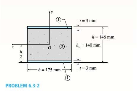
A sandwich beam having steel faces enclosing a plastic core is subjected to a bending moment M = 5 kN · m. The thickness of each steel face is 1 = 3 mm with modulus of elasticity E = 200 GPa, The height of the plastic core is hp= 140 mm, and its modulus of elasticity is Ep= 800 MPa. The overall dimensions of the beam are h = 146 mm and h = 175 mm.
Using the transformed-section method, determine the maximum tensile and compressive stresses in the faces and the core.
Expert Solution & Answer

Trending nowThis is a popular solution!

Students have asked these similar questions
Exercises
Find the solution of the following Differential Equations
1) y" + y = 3x²
3)
"+2y+3y=27x
5) y"+y=6sin(x)
7) y"+4y+4y = 18 cosh(x)
9) (4)-5y"+4y = 10 cos(x)
11) y"+y=x²+x
13) y"-2y+y=e*
15) y+2y"-y'-2y=1-4x³
2) y"+2y' + y = x²
4) "+y=-30 sin(4x)
6) y"+4y+3y=sin(x)+2 cos(x)
8) y"-2y+2y= 2e* cos(x)
10) y+y-2y=3e*
12) y"-y=e*
14) y"+y+y=x+4x³ +12x²
16) y"-2y+2y=2e* cos(x)
The state of stress at a point is σ = -4.00 kpsi, σy = 16.00 kpsi, σ = -14.00 kpsi, Try = 11.00 kpsi,
Tyz = 8.000 kpsi, and T = -14.00 kpsi.
Determine the principal stresses.
The principal normal stress σ₁ is determined to be [
The principal normal stress σ2 is determined to be [
The principal normal stress σ3 is determined to be
kpsi.
kpsi.
The principal shear stress 71/2 is determined to be [
The principal shear stress 7½ is determined to be [
The principal shear stress T₁/, is determined to be [
kpsi.
kpsi.
kpsi.
kpsi.
Repeat Problem 28, except using a shaft that is rotatingand transmitting a torque of 150 N * m from the left bearing to the middle of the shaft. Also, there is a profile keyseat at the middle under the load.
(I want to understand this problem)
Chapter 6 Solutions
Mechanics of Materials, SI Edition
Ch. 6 - A composite beam is constructed using a steel...Ch. 6 - A wood beam is strengthened using two steel plates...Ch. 6 - A composite beam consisting of fiberglass faces...Ch. 6 - A wood beam with cross-sectional dimensions 200 mm...Ch. 6 - A hollow box beam is constructed with webs of...Ch. 6 - A r o lukI f/frm f «m t ub e of ou t sid e d ia...Ch. 6 - A beam with a guided support and 10-ft span...Ch. 6 - A plastic-lined steel pipe has the cross-sectional...Ch. 6 - The cross section of a sand wie h beam consisting...Ch. 6 - The cross section of a sandwich beam consisting of...
Ch. 6 - A bimetallic beam used in a temperature-control...Ch. 6 - A simply supported composite beam 3 m long carries...Ch. 6 - A simply supported wooden I-beam with a 12-ft span...Ch. 6 - -14 A simply supported composite beam with a 3.6 m...Ch. 6 - -15 A composite beam is constructed froma wood...Ch. 6 - A wood beam in a historic theater is reinforced...Ch. 6 - Repeat Problem 6.2-1 but now assume that the steel...Ch. 6 - Repeat Problem 6.2-17 but now use a...Ch. 6 - A sandwich beam having steel faces enclosing a...Ch. 6 - A wood beam 8 in. wide and 12 in. deep (nominal...Ch. 6 - A simple beam of span length 3.2 m carries a...Ch. 6 - A simple beam that is 18 ft long supports a...Ch. 6 - The composite beam shown in the figure is simply...Ch. 6 - The cross section of a beam made of thin strips of...Ch. 6 - Consider the preceding problem if the beam has...Ch. 6 - A simple beam thai is IS ft long supports a...Ch. 6 - The cross section of a composite beam made of...Ch. 6 - A beam is constructed of two angle sections, each...Ch. 6 - The cross section of a bimetallic strip is shown...Ch. 6 - A W 12 x 50 steel wide-flange beam and a segment...Ch. 6 - A reinforced concrete beam (see figure) is acted...Ch. 6 - A reinforced concrete T-beam (see figure) is acted...Ch. 6 - A reinforced concrete slab (see figure) is...Ch. 6 - A wood beam reinforced using two channels is...Ch. 6 - A wood beam reinforced by an aluminum channel...Ch. 6 - A beam with a rectangular cross section supports...Ch. 6 - A wood beam with a rectangular cross section (see...Ch. 6 - Solve the preceding problem for the following...Ch. 6 - A simply supported wide-flange beam of span length...Ch. 6 - Solve the preceding problem using the fol...Ch. 6 - A wood cantilever beam with a rectangular cross...Ch. 6 - Solve the preceding problem for a cantilever beam...Ch. 6 - A 2-m-long cantilever beam is constructed using a...Ch. 6 - A wood beam AB with a rectangular cross section (4...Ch. 6 - A steel beam of I-section (see figure) is simply...Ch. 6 - A cantilever beam with a wide-flange cross section...Ch. 6 - Solve the preceding problem using a W 310 x 129...Ch. 6 - A cantilever beam of W 12 × 14 section and length...Ch. 6 - A cantilever beam built up from two channel...Ch. 6 - A built-Lip I-section steel beam with channels...Ch. 6 - Repeat Problem 6.4-14 but use the configuration of...Ch. 6 - A beam with a channel section is subjected to a...Ch. 6 - A beam with a channel section is subjected to a...Ch. 6 - An angle section with equal legs is subjected to a...Ch. 6 - An angle section with equal legs is subjected to a...Ch. 6 - A beam made up all woun equal leg angles is...Ch. 6 - The Z-section of Example D-7 is subjected to M = 5...Ch. 6 - The cross section of a steel beam is constructed...Ch. 6 - The cross section of a steel beam is shown in the...Ch. 6 - A beam with a semicircular cross section of radius...Ch. 6 - .10 A built-up bourn supporting a condominium...Ch. 6 - Asteelpost (E = 30 × 106 psi) having thickness t =...Ch. 6 - A C 200 x 17.1 channel section has an angle with...Ch. 6 - A cold-formed steel section is made by folding a...Ch. 6 - A simple beam with a W 10 x 30 wide-flange cross...Ch. 6 - Solve the preceding problem for a W 250 × 44.8...Ch. 6 - A beam of wide-flange shape, W 8 x 28, has the...Ch. 6 - Solve the preceding problem for a W 200 × 41,7...Ch. 6 - Calculate the distance e from the cent crime of...Ch. 6 - Calculate the distance e from the centerline of...Ch. 6 - The cross section of an unbalanced wide-flange...Ch. 6 - The cross section of an unbalanced wide-flange...Ch. 6 - The cross section of a channel beam with double...Ch. 6 - The cross section of a slit circular tube of...Ch. 6 - The cross section of a slit square tube of...Ch. 6 - The cross section of a slit rectangular tube of...Ch. 6 - A U-shaped cross section of constant thickness is...Ch. 6 - Derive the following formula for the distance e...Ch. 6 - Derive the following formula for the distance e...Ch. 6 - The cross section of a sign post of constant...Ch. 6 - A cross section in the shape of a circular arc of...Ch. 6 - Determine the shape factor f for a cross section...Ch. 6 - (a) Determine the shape factor/for a hollow...Ch. 6 - A propped cantilever beam of length L = 54 in....Ch. 6 - A steel beam of rectangular cross section is 40 mm...Ch. 6 - .5 Calculate the shape factor j for the...Ch. 6 - Solve the preceding problem for a wide-flange beam...Ch. 6 - Determine the plastic modulus Z and shape...Ch. 6 - Prob. 6.10.8PCh. 6 - Prob. 6.10.9PCh. 6 - Prob. 6.10.10PCh. 6 - A hollow box beam with height h = 16 in,, width h...Ch. 6 - Solve the preceding problem for a box beam with...Ch. 6 - A hollow box beam with height h = 9.5 in., inside...Ch. 6 - Solve the preceding problem for a box beam with...Ch. 6 - The hollow box beam shown in the figure is...Ch. 6 - Prob. 6.10.16PCh. 6 - Prob. 6.10.17PCh. 6 - A singly symmetric beam with a T-section (see...Ch. 6 - A wide-flange beam with an unbalanced cross...Ch. 6 - .20 Determine the plastic moment Mpfor beam having...
Knowledge Booster


Learn more about
Need a deep-dive on the concept behind this application? Look no further. Learn more about this topic, mechanical-engineering and related others by exploring similar questions and additional content below.Similar questions
- Prob 2. The material distorts into the dashed position shown. Determine the average normal strains &x, Ey and the shear strain Yxy at A, and the average normal strain along line BE. 50 mm B 200 mm 15 mm 30 mm D ΕΙ 50 mm x A 150 mm Farrow_forwardProb 3. The triangular plate is fixed at its base, and its apex A is given a horizontal displacement of 5 mm. Determine the shear strain, Yxy, at A. Prob 4. The triangular plate is fixed at its base, and its apex A is given a horizontal displacement of 5 mm. Determine the average normal strain & along the x axis. Prob 5. The triangular plate is fixed at its base, and its apex A is given a horizontal displacement of 5 mm. Determine the average normal strain &x along the x' axis. x' 45° 800 mm 45° 45% 800 mm 5 mmarrow_forwardAn airplane lands on the straight runaway, originally travelling at 110 ft/s when s = 0. If it is subjected to the decelerations shown, determine the time t' needed to stop the plane and construct the s -t graph for the motion. draw a graph and show all work step by steparrow_forward
- dny dn-1y dn-1u dn-24 +a1 + + Any = bi +b₂- + +bnu. dtn dtn-1 dtn-1 dtn-2 a) Let be a root of the characteristic equation 1 sn+a1sn- + +an = : 0. Show that if u(t) = 0, the differential equation has the solution y(t) = e\t. b) Let к be a zero of the polynomial b(s) = b₁s-1+b2sn−2+ Show that if the input is u(t) equation that is identically zero. = .. +bn. ekt, then there is a solution to the differentialarrow_forwardB 60 ft WAB AB 30% : The crane's telescopic boom rotates with the angular velocity w = 0.06 rad/s and angular acceleration a = 0.07 rad/s². At the same instant, the boom is extending with a constant speed of 0.8 ft/s, measured relative to the boom. Determine the magnitude of the acceleration of point B at this instant.arrow_forwardThe motion of peg P is constrained by the lemniscate curved slot in OB and by the slotted arm OA. (Figure 1) If OA rotates counterclockwise with a constant angular velocity of 0 = 3 rad/s, determine the magnitude of the velocity of peg P at 0 = 30°. Express your answer to three significant figures and include the appropriate units. Determine the magnitude of the acceleration of peg P at 0 = 30°. Express your answer to three significant figures and include the appropriate units. 0 (4 cos 2 0)m² B Aarrow_forward
- 5: The structure shown was designed to support a30-kN load. It consists of a boom AB with a 30 x 50-mmrectangular cross section and a rod BC with a 20-mm-diametercircular cross section. The boom and the rod are connected bya pin at B and are supported by pins and brackets at A and C,respectively.1. Calculate the normal stress in boom AB and rod BC,indicate if in tension or compression.2. Calculate the shear stress of pins at A, B and C.3. Calculate the bearing stresses at A in member AB,and in the bracket.arrow_forward4: The boom AC is a 4-in. square steel tube with a wallthickness of 0.25 in. The boom is supported by the 0.5-in.-diameter pinat A, and the 0.375-in.-diameter cable BC. The working stresses are 25ksi for the cable, 18 ksi for the boom, and 13.6 ksi for shear in the pin.Neglect the weight of the boom.1. Calculate the maximum value of P (kips) based on boom compression and the maximum value of P (kips) based on tension in the cable.2. Calculate the maximum value of P (kips) based on shear in pin.arrow_forward3: A steel strut S serving as a brace for a boat hoist transmits a compressive force P = 54 kN to the deck of a pier as shown in Fig. STR-08. The strut has a hollow square cross section with a wall thickness t =12mm and the angle θ between the strut and the horizontal is 40°. A pin through the strut transmits the compressive force from the strut to two gusset plates G that are welded to the base plate B. Four anchor bolts fasten the base plate to the deck. The diameter of the pin is 20mm, the thickness of the gusset plates is 16mm, the thickness of the base plate is 8mm, and the diameter of the anchor bolts is 12mm. Disregard any friction between the base plate and the deck.1. Determine the shear stress in the pin, in MPa and the shear stress in the anchor bolts, in MPa.2. Determine the bearing stress in the strut holes, in MPa.arrow_forward
- 1. In the figure, the beam, W410x67, with 9 mm web thicknesssubjects the girder, W530x109 with 12 mm web thickness to a shear load,P (kN). 2L – 90 mm × 90 mm × 6 mm with bolts frame the beam to thegirder.Given: S1 = S2 = S5 = 40 mm; S3 = 75 mm; S4 = 110 mmAllowable Stresses are as follows:Bolt shear stress, Fv = 125 MPaBolt bearing stress, Fp = 510 MPa1. Determine the allowable load, P (kN), based on the shearcapacity of the 4 – 25 mm diameter bolts (4 – d1) and calculate the allowable load, P (kN), based on bolt bearing stress on the web of the beam.2. If P = 450 kN, determine the minimum diameter (mm) of 4 – d1based on allowable bolt shear stress and bearing stress of thebeam web.arrow_forward6: The 6-kN load P is supported by two wooden members of 75 x 125-mm uniform cross section that are joined by the simple glued scarf splice shown.1. Calculate the normal stress in the glue, in MPa.2. Calculate the shear stress in the glue, in MPa.arrow_forwardUsing Matlab calculate the following performance characteristics for a Tesla Model S undergoing the 4506 drive cycle test Prated Trated Ebat 80kW 254 Nm 85kWh/1645kg MUEH A rwheel 0.315M 133.3 C 0.491 Ng ng 7g 8.190.315 8.19 0.315 7ed= 85% Ebpt 35-956 DRIVE AXLE Ebfb chę =85% V Minverter H/A Battery Charger En AC Pry 9) required energy output from the motor to drive this cycle Cassume no regenerative braking) b) range of the Tesla Model S for this drive cycle (assume no regenerative breaking c) estimated mpge cycle of the Tesla Model S for this drive Cassume no regenerative breaking) d) Recalculate parts abc now assuming you can regenerate returns correctly due to inefficiency. from braking. Be careful to handle the diminishing energy braking makes in terms of required e) Quantify the percentage difference that regenerative required energy, range and mpge, DI L Ta a ra OLarrow_forward
arrow_back_ios
SEE MORE QUESTIONS
arrow_forward_ios
Recommended textbooks for you
 Mechanics of Materials (MindTap Course List)Mechanical EngineeringISBN:9781337093347Author:Barry J. Goodno, James M. GerePublisher:Cengage Learning
Mechanics of Materials (MindTap Course List)
Mechanical Engineering
ISBN:9781337093347
Author:Barry J. Goodno, James M. Gere
Publisher:Cengage Learning
Everything About COMBINED LOADING in 10 Minutes! Mechanics of Materials; Author: Less Boring Lectures;https://www.youtube.com/watch?v=N-PlI900hSg;License: Standard youtube license