
Concept explainers
Videos
A 150 Ib block rests on a horizontal floor. The coefficient of friction between the block and the floor is 0.30. A pull of 40 lb, acting upward at an angle of 30° to the horizontal, is applied to the block. Determine whether or not the block will slide.
The block will slide or not.
Answer to Problem 6.1P
The block will not slide.
Explanation of Solution
Given:
Weight of block
Angle acting at pulling force on the block
Pulling force on block
Co-efficient of static friction
Free body diagram.
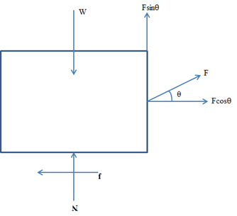
First equating the vertical force to zero to find N.
Therefore, the block is not going to move as the frictional force is more than the pulling force.
Conclusion:
Force on the block is not going to slide because the applied force on the block is not going to be enough to overcome the frictional force.
Want to see more full solutions like this?
Chapter 6 Solutions
Applied Statics and Strength of Materials (6th Edition)
Additional Engineering Textbook Solutions
Java: An Introduction to Problem Solving and Programming (8th Edition)
Concepts Of Programming Languages
Computer Science: An Overview (13th Edition) (What's New in Computer Science)
Electric Circuits. (11th Edition)
Introduction To Programming Using Visual Basic (11th Edition)
Thinking Like an Engineer: An Active Learning Approach (4th Edition)


- Water is condensing on a square plate (0.5 m x 0.5 m) placed verCcally. If the desired rate ofcondensaCon is 0.016 kJ/s, determine the necessary surface temperature of the plate at atmosphericpressure. Assume the film temperature of 90 o C for evaluaCon of fluid properCes of water and thesurface temperature of 80 o C for the evaluaCon of modified latent heat of vaporizaConarrow_forwardWater at 20 o C enters the 4 cm-diameter, 14 m-long tube at a rate of 0.8 kg/s. The surfacetemperature of the pipe is maintained at 165 o Cby condensing geothermal stream at the shellside of the heat exchanger. Use water properCesat 85 o C for all calculaCons.(a) Show that the water flow is turbulent and thermally fully developed. (b) EsCmate the heat transfer coefficient for convecCve heat transfer from the pipe to the water. For a fully developed turbulent flow within the smooth pipe, the Nu number can becalculated from the following equaCon:(c) Calculate the exit temperature of the water. (d) Share your opinion on whether the use of water properties at 85°C is appropriate. Yes or No because:arrow_forwardConsider a hot automotive engine, which can beapproximated as a 0.5-m-high, 0.40-m-wide, and 0.8-m-long rectangular block. The bottom surface of the block isat a temperature of 100°C and has an emissivity of 0.95.The ambient air is at 20°C, and the road surface is at25°C. Determine the rate of heat transfer from the bottomsurface of the engine block by convection and radiationas the car travels at a velocity of 80 km/h. Assume theflow to be turbulent over the entire surface because of theconstant agitation of the engine block. a) Calculate convective heat transfer coefficient (h). b) Calculate the total heat transfer ratearrow_forward
- 8 mm- Top view -200 mm-180 mm- D B B 12 mm Side view B -8 mm D PROBLEM 1.56 In an alternative design for the structure of Prob. 1.55, a pin of 10-mm-diameter is to be used at A. Assuming that all other specifications remain unchanged, determine the allowable load P if an overall factor of safety of 3.0 is desired. PROBLEM 1.55 In the structure shown, an 8- mm-diameter pin is used at A, and 12-mm- diameter pins are used at B and D. Knowing that the ultimate shearing stress is 100 MPa at all connections and that the ultimate normal stress is 250 MPa in each of the two links joining B and D, determine the allowable load P if an overall factor of safety of 3.0 is desired. 20 mm P 8 mm- 12 mm- Front viewarrow_forwardWhere on the beam below is the Maximum Deflection likely to occur? 2P A "ती Point A Point B Point C Point D Point B or Point D ८ B पarrow_forwardSign in ||! PDE 321 proje X IMB321 PDF Lecture 5 X PDF Planet Ec X PDF Planet Ec X PDF PEABWX PDF meeting x PDF GSS Quo X PDF File C:/Users/KHULEKANI/Downloads/CIVE%20281%20Ass-2.pdf Draw | | All | a | Ask Copilot + 1 of 7 | D SOLUTION B PROBLEM 12.16 Block 4 has a mass of 40 kg, and block B has a mass of 8 kg. The coefficients of friction between all surfaces of contact are μ, = 0.20 H = 0.15. Knowing that P = 50 N→, determine (a) the acceleration of block B, (b) the tension in the cord. Constraint of cable: 2x + (x-x1) = x + x = constant. a+ag = 0, or aB = -a Assume that block A moves down and block B moves up. Block B: +/ΣF, = 0: NAB - WB cos 0 = 0 =ma: -T+μN + Wsin = We as g + ΣΕ We Eliminate NAB and aB- NAB B Nas HN UNA A NA -T+W(sin+μcоsе) = WB- g VD"M- g Block A: +/ΣF, = 0: NA-NAB - W₁cos + Psinė = 0 N₁ = N AB+W cose - Psin = (WB+WA)cose - Psinė ΣF=ma -T+Wsino-FAB-F + Pcos = CIVE 281 X + Ждал g Q | го || حالم ☑arrow_forward
- Where on the below beam is the Maxiumum Slope likely to occur? 120 Point A Point B Point C Point B or Point C B сarrow_forwardA very thin metallic sheet is placed between two wood plates of different thicknesses. Theplates are firmly pressed together and electricity is passed through the sheet. The exposed surfaces ofthe two plates lose heat to the ambient fluid by convection. Assume uniform heating at the interface.Neglect end effects and assume steady state.[a] Will the heat transfer through the two plates be the same? Explain.[b] Will the exposed surfaces be at the same temperature? Explainarrow_forwardDesign consideration requires that the surface of a small electronic package be maintained at atemperature not to exceed 82 o C. Noise constraints rule out the use of fans. The power dissipated inthe package is 35 watts and the surface area is 520 cm2 . The ambient temperature and surroundingwalls are assumed to be at 24 o C. The heat transfer coefficient is estimated to be 9.2 W/m2- oC andsurface emissivity is 0.7. Will the package dissipate the required power without violating designconstraints?arrow_forward
- Consider radiation from a small surface at 100 oC which is enclosed by a much larger surface at24 o C. Determine the percent increase in the radiation heat transfer if the temperature of the smallsurface is doubled.arrow_forwardA small electronic package with a surface area of 820 cm2 is placed in a room where the airtemperature is 28 o C. The heat transfer coefficient is 7.3 W/m2 - o C. You are asked to determine if it isjustified to neglect heat loss from the package by radiation. Assume a uniform surface temperature of78 o C and surface emissivity of 0.65 Assume further that room’s walls and ceiling are at a uniformtemperature of 16 o C.arrow_forwardA hollow metal sphere of outer radius or = 2 cm is heated internally with a variable output electricheater. The sphere loses heat from its surface by convection and radiation. The heat transfercoefficient is 22 W/ m2 - o C and surface emissivity is 0.92. The ambient fluid temperature is 20 o C andthe surroundings temperature is 14 oC. Construct a graph of the surface temperature corresponding toheating rates ranging from zero to 100 watts. Assume steady state. Use a simplified model forradiation exchange based on a small gray surface enclosed by a much larger surface at 14 o C.arrow_forward
 International Edition---engineering Mechanics: St...Mechanical EngineeringISBN:9781305501607Author:Andrew Pytel And Jaan KiusalaasPublisher:CENGAGE L