
Applied Statics and Strength of Materials (6th Edition)
6th Edition
ISBN: 9780133840544
Author: George F. Limbrunner, Craig D'Allaird, Leonard Spiegel
Publisher: PEARSON
expand_more
expand_more
format_list_bulleted
Videos
Textbook Question
Chapter 6, Problem 6.12P
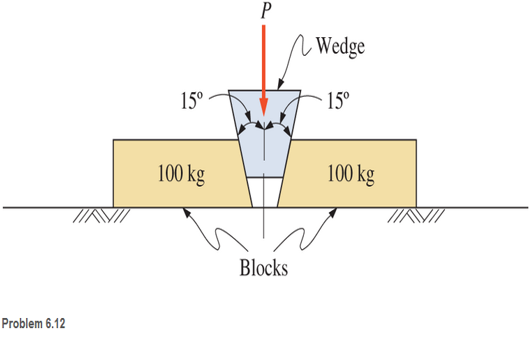
Two blocks, each having a mass of 100 kg and resting on a horizontal surface, are to be pushed apart using a 30° wedge, as shown. The coefficient of static friction for all contact surfaces is 0.25. Calculate the vertical force P required to start the wedge and the blocks in motion.
Expert Solution & Answer
Want to see the full answer?
Check out a sample textbook solution
Students have asked these similar questions
نصاف
Sheet
Asteel bar of rectangular cross section with
dimension
Shown in fig. below. This bar is
as
Connected toawell. Using welded Join a long the sides
als only find the weld size (h). Where:
Tall = 35 MN/M²
F=213.30
answer/h=
4.04
☐
Yomm
Soomm
100mm
FEA
FEA
Chapter 6 Solutions
Applied Statics and Strength of Materials (6th Edition)
Ch. 6 - A 150 Ib block rests on a horizontal floor. The...Ch. 6 - A 200 lb block rests on a horizontal surface. The...Ch. 6 - A tool locker having a mass of 140 kg rests on a...Ch. 6 - A body weighing 100 lb rests on an inclined plane,...Ch. 6 - For Problem 6.4 , compute the friction force F...Ch. 6 - Block A in the figure shown has a mass of 10 kg...Ch. 6 - Compute the horizontal force P required to cause...Ch. 6 - Prob. 6.8PCh. 6 - Calculate the magnitude of the force P, acting as...Ch. 6 - For the block-and-wedge system shown in Figure...
Ch. 6 - Calculate the value of the horizontal force P...Ch. 6 - Two blocks, each having a mass of 100 kg and...Ch. 6 - Calculate the force P required to move the wedges...Ch. 6 - A heavy machine is lowered into a pit by means of...Ch. 6 - Calculate the maximum weight that the person in...Ch. 6 - A flat belt passes halfway around a...Ch. 6 - A belt-and-pulley arrangement has a maximum belt...Ch. 6 - Rework Problem 6.17 for a V-belt with a 40° groove...Ch. 6 - A mass of 320 kg is prevented from falling by a...Ch. 6 - A belt is wrapped around a pulley for 180°. The...Ch. 6 - A jackscrew has a square thread with a pitch of...Ch. 6 - The mean diameter of a square-threaded jackscrew...Ch. 6 - The woodworking vise shown is designed for a...Ch. 6 - A square-threaded screw is used ii a press, shown,...Ch. 6 - For the following computer problems, any...Ch. 6 - Prob. 6.26CPCh. 6 - For the following computer problems, any...Ch. 6 - 6.28 A horizontal force of 18 lb is required to...Ch. 6 - 6.29 A 90-Ib block lying on a rough horizontal...Ch. 6 - 6.30 The tool locker of Problem 6.3 is 0.8 m by...Ch. 6 - Prob. 6.31SPCh. 6 - A 50-lb block rests on a rough inclined plane. If...Ch. 6 - If in Problem 6-32 the plane has an inclination...Ch. 6 - A 325-lb block rests on a plane inclined 25° with...Ch. 6 - A 47 lb body is supported on a plane inclined 33°...Ch. 6 - Prob. 6.36SPCh. 6 - In the figure shown, block A weighs 200 lb and...Ch. 6 - Calculate the magnitude of the horizontal force P,...Ch. 6 - In the figure shown, the coefficient of static...Ch. 6 - A 500-lb block rests on a horizontal surface, as...Ch. 6 - A ladder, 8 m long and having a mass of 25 kg,...Ch. 6 - The ladder shown is supported by a horizontal...Ch. 6 - 6.43 A 16-ft ladder weighing 62 lb (assumed...Ch. 6 - Prob. 6.44SPCh. 6 - 6.45 Compute the minimum weight of block B that...Ch. 6 - Prob. 6.46SPCh. 6 - Prob. 6.47SPCh. 6 - Prob. 6.48SPCh. 6 - Prob. 6.49SPCh. 6 - Prob. 6.50SPCh. 6 - Calculate the force P necessary to start the block...Ch. 6 - A machine having a mass of 500 kg is to be raised...Ch. 6 - 6.53 A ship may exert an estimated pull of 8000 lb...Ch. 6 - A sailor wraps a heavy rope around a bollard (a...Ch. 6 - When a large rope is wrapped twice around a post,...Ch. 6 - A band brake is in contact with drum C through an...Ch. 6 - Prob. 6.57SPCh. 6 - The mean diameter of a square-threaded jackscrew...Ch. 6 - The manually operated apple cider press shown has...
Knowledge Booster


Learn more about
Need a deep-dive on the concept behind this application? Look no further. Learn more about this topic, mechanical-engineering and related others by exploring similar questions and additional content below.Similar questions
- HELP?arrow_forwardTrue and False Indicate if each statement is true or false. T/F 1. Rule #1 protects the function of assembly. T/F 2. One of the fundamental dimensioning rules requires all dimensions apply in the free-state condition for rigid parts. T/F 3. The fundamental dimensioning rules that apply on a drawing must be listed in the general notes. T/F 4. Where Rule #1 applies to a drawing, it limits the form of every feature of size on the drawing. T/F 5. Rule #1 limits the variation between features of size on a part. T/F 6. The designer must specify on the drawing which features of size use Rule #1. T/F T/F T/F 7. Rule #1 applies to nonrigid parts (in the unrestrained state). 8. A GO gage is a fixed-limit gage. 9. Rule #1 requires that the form of an individual regular feature of size is controlled by its limits of sizearrow_forwardFEAarrow_forward
- Please also draw the FBDsarrow_forwardDesign Description: Fresh water tank, immersed in an oil tank.a) Water tank:a. Shape: Cylindricalb. Radius: 1 meterc. Height: 3 metersd. Bottom airlock: 0.2m x 0.2m. b) Oil tank:a. Shape: cylindricalb. Radius: 4 metersc. Oil density: 850 kg/m³ Determine:a) The pressure experienced by an airlock at the bottom of the tank with water.b) The force and direction necessary to open the lock, suppose the lock weighs 20 Newtons, suppose the lock opens outwards. The image is for illustrative purposes, the immersed cylinder does not reach the bottomarrow_forwardNeed help!arrow_forward
arrow_back_ios
SEE MORE QUESTIONS
arrow_forward_ios
Recommended textbooks for you
 International Edition---engineering Mechanics: St...Mechanical EngineeringISBN:9781305501607Author:Andrew Pytel And Jaan KiusalaasPublisher:CENGAGE L
International Edition---engineering Mechanics: St...
Mechanical Engineering
ISBN:9781305501607
Author:Andrew Pytel And Jaan Kiusalaas
Publisher:CENGAGE L
How to balance a see saw using moments example problem; Author: Engineer4Free;https://www.youtube.com/watch?v=d7tX37j-iHU;License: Standard Youtube License