
The steady flow rates in each pipe and the difference in both the results.
Answer to Problem 6.122P
The flow rates found in this part is 5.2 times lower than that of part P6.121. It is because the flow rate is dependent on the cross-sectional area. Therefore, reducing the diameter from 28 to 15 will decrease the amount of flow rate.
Explanation of Solution
Given information:
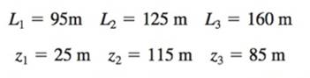
Diameter of all pipes are
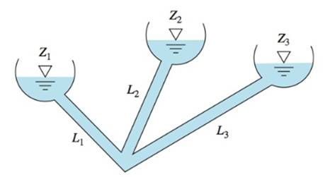
At three reservoir junction, if all flows are considered positive towards the junction, then
Assuming the gauge pressure
To solve this type of problems, we should guess the position of
If the
Calculation:
First of all,
Guess
The roughness ratio for all pipes will be,
To find Reynolds’s number,
Therefore,
The friction factor will be equal to,
Therefore, according to the below equation
According to the above result, the Reynolds’s number will be
To find the flow rate,
The flow in pipe 1 is considered as flow away from the junction
Similarly for pipe 2,
To find Reynolds’s number,
 Try
Try
Therefore,
The friction factor will be the same.
According to the above result, the Reynolds’s number will be
To find the flow rate,
The flow in pipe 2 is considered as flow towards the junction.
For pipe 3,
Therefore,
Hence
Try
Therefore,
The friction factor will be the same.
According to the above result, the Reynolds’s number will be
To find the flow rate,
The flow in pipe 1 is considered as flow away from the junction
Similarly for pipe 2,
To find Reynolds’s number,
Therefore,
The friction factor will be same.
According to the above result, the Reynolds’s number will be
To find the flow rate,
The flow in pipe 2 is considered as flow towards the junction.
Similarly for pipe 3,
To find Reynolds’s number,
Try
Therefore,
The friction factor will be equal to,
According to above result, the Reynolds’s number will be
To find the flow rate,
The flow in pipe 3 is considered as flow towards the junction.
Therefore the flow rate will be,
By further iteration, we can get this close to zero, but for now, according to the obtained results, we can say,
In part P6.121, the flow rate were,
Therefore, we can say,
The flow rates found in this part is 5.2 times lower than that of part P6.121. It’s because the flow rate is dependent on the cross-sectional area. Therefore, reducing the diameter from 28 to 15 will decrease the amount of flow rate.
Conclusion:
The flow rates in each pipe is equal to,
The flow rates are 5.2 times lower than that of part P6.121.
Want to see more full solutions like this?
Chapter 6 Solutions
Fluid Mechanics, 8 Ed

- (read image) Answer:arrow_forward(read image) Answer:arrow_forward2nd Law of Thermodynamics A 1.5-ft3 rigid tank contains saturated refrigerant-134 at 170 psia. Initially, 20 percent of the volume isoccupied by liquid and the rest by vapor. A valve at the top of the tank is now opened, and vapor is allowedto escape slowly from the tank. Heat is transferred to the refrigerant such that the pressure inside the tankremains constant. The valve is closed when the last drop of liquid in the tank is vaporized. Determine thetotal heat transfer for this process.arrow_forward
- Draw the shear and bending-moment diagrams for the beam and loading shown, and determine the maximum normal stress due to bending. 4.8 kips/ft 32 kips B C D E I Hinge 8 ft. 2 ft 5 ft 5 ft W12 x 40arrow_forward2nd Law of Thermodynamics A rigid, insulated tank that is initially evacuated is connected through a valve to the supply line that carrieshelium at 300 kPa and 140◦C. Now the valve is opened, and helium is allowed to flow into the tank until thepressure reaches 300 kPa, at which point the valve is closed. Determine the flow work of the helium in thesupply line and the final temperature of the helium in the tank.arrow_forwardDraw the shear and bending-moment diagrams for the beam and loading shown, and determine the maximum normal stress due to bending. 5 kips 10 kips B I W14 x 22 -5 ft -8 ft 5 ft-arrow_forward
- 2nd Law of Thermodynamics Liquid water at 200 kPa and 25◦C is heated in a chamber by mixing it with superheated steam at 200 kPaand 250◦C. cold water enters the chamber at a rate of 2 kg/s. If the mixture leaves the mixing chamber at50◦C, determine the mass flow rate of the superheated steam required.arrow_forwardThe 2nd Law of Thermodynamics Refrigerant-134a enters the compressor of a refrigeration system as saturated vapor at 0.16 MPa, and leavesas superheated vapor at 0.9 MPa and 70◦C at a rate of 0.08 kg/s. Determine the rates of energy transfers bymass into and out of the compressor. Assume the kinetic and potential energies are negligible.arrow_forward2nd Law of Thermodynamics Water enters the tubes of a cold plate at 65◦C with an average velocity of 50 ft/min and leaves at 110◦F. Thediameter of the tubes is 0.2 in. Assuming 20 percent of the heat generated is dissipated from the componentsto the surroundings by convection and radiation, and the remaining 80 percent is removed by the coolingwater, determine the amount of heat generated by the electronic devices mounted on the cold plate.arrow_forward
- The 2nd Law of Thermodynamics Refrigerant-134a enters a diffuser steadily as saturated vapor 500 kPa with a velocity of 170 m/s, and it leavesat 600 kPa and 50◦C. the refrigerant is gaining heat at a rate of 2.5 kJ/s as it passes through the diffuser. Ifthe exit area is 75 percent greater than the inlet area, determine (a) the exit velocity (b) the mass flow rate of the refrigerant.arrow_forward2nd Law of Thermodynamics Refrigerant-134a is throttled from the saturated liquid state at 850 kPa to a pressure of 200 kPa. Determinethe temperature drop during this process and the final specific volume of the refrigerant.arrow_forward2nd Law of Thermodynamics An adiabatic gas turbine expands air at 1350 kPa and 525◦C to 125 kPa and 130◦C. Air enters the tur-bine through a 0.15-m2 opening with an average velocity of 50 m/s, and exhausts through a 1-m2 opening.Determine (a) the mass flow rate of air through the turbine (b) the power produced by the turbine.arrow_forward
 Elements Of ElectromagneticsMechanical EngineeringISBN:9780190698614Author:Sadiku, Matthew N. O.Publisher:Oxford University Press
 Mechanics of Materials (10th Edition)Mechanical EngineeringISBN:9780134319650Author:Russell C. HibbelerPublisher:PEARSON
 Thermodynamics: An Engineering ApproachMechanical EngineeringISBN:9781259822674Author:Yunus A. Cengel Dr., Michael A. BolesPublisher:McGraw-Hill Education
 Control Systems EngineeringMechanical EngineeringISBN:9781118170519Author:Norman S. NisePublisher:WILEY
 Mechanics of Materials (MindTap Course List)Mechanical EngineeringISBN:9781337093347Author:Barry J. Goodno, James M. GerePublisher:Cengage Learning
 Engineering Mechanics: StaticsMechanical EngineeringISBN:9781118807330Author:James L. Meriam, L. G. Kraige, J. N. BoltonPublisher:WILEY