
Mechanics Of Materials, Si Edition
9th Edition
ISBN: 9789810694364
Author: Russell C Hibbeler
Publisher: Pearson Education
expand_more
expand_more
format_list_bulleted
Videos
Textbook Question
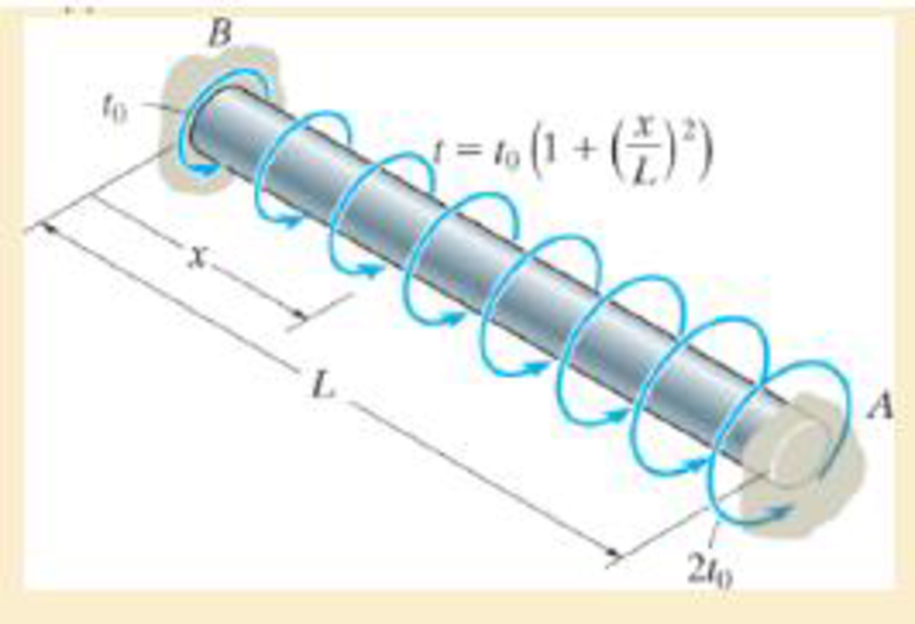
Chapter 5.5, Problem 5.94P
Determine the reactions at the fixed supports A and B.
Expert Solution & Answer
Want to see the full answer?
Check out a sample textbook solution
Students have asked these similar questions
Hints: Find the closed loop transfer function and then plot the step response for diFerentvalues of K in MATLAB. Show step response plot for different values of K.
Auto Controls
Show solutions and provide matlab code
NO COPIED ANSWERS OR WILL REPORT!!!!
Use own solution
what is shear stress and normal? how to tell them while calculating?
12 mm
45 mm
20 kN
20 kN
12 mm
45 mm
PROBLEM 1.61
For the assembly and loading of Problem 1.60, determine (a) the
average shearing stress in the pin at C, (b) the average bearing stress at
C in member BC, (c) the average bearing stress at B in member BC.
PROBLEM 1.60 Two horizontal 20-kN forces are applied to pin B of
the assembly shown. Knowing that a pin of 20-mm diameter is used at
each connection, determine the maximum value of the average normal
stress (a) in link AB, (b) in link BC.
Chapter 5 Solutions
Mechanics Of Materials, Si Edition
Ch. 5.3 - Determine the internal torque at each section and...Ch. 5.3 - Determine the. internal torque at each section and...Ch. 5.3 - The solid and hollow shafts are each subjected to...Ch. 5.3 - The motor delivers 10 hp to the shaft. If it...Ch. 5.3 - The solid circular shaft is subjected to an...Ch. 5.3 - The hollow circular shaft is subjected to an...Ch. 5.3 - The shaft is hollow from A to B and solid from B...Ch. 5.3 - Determine the maximum shear stress in the...Ch. 5.3 - Determine the maximum shear stress in the shaft at...Ch. 5.3 - Determine the shear stress a: point A on the...
Ch. 5.3 - The solid 50-mm-diameter shaft is subjected to the...Ch. 5.3 - The gear motor can develop 3 hp when it turns at...Ch. 5.3 - The solid shaft of radius r is subjected to a...Ch. 5.3 - The solid shaft of radius r is subjected to a...Ch. 5.3 - 5-3. The solid shaft is fixed to the support at C...Ch. 5.3 - The copper pipe has an outer diameter of 40 mm and...Ch. 5.3 - The copper pipe has an outer diameter of 2.50 in....Ch. 5.3 - Prob. 5.6PCh. 5.3 - Prob. 5.7PCh. 5.3 - The solid 30-mm-diameter shaft is used to transmit...Ch. 5.3 - The solid shaft is fixed to the support at C and...Ch. 5.3 - Prob. 5.10PCh. 5.3 - The assembly consists of two sections of...Ch. 5.3 - Prob. 5.12PCh. 5.3 - 5-13. If The tubular shaft is made from material...Ch. 5.3 - A steel tube having an outer diameter of 2.5 in....Ch. 5.3 - Prob. 5.15PCh. 5.3 - Prob. 5.16PCh. 5.3 - The rod has a diameter of 1 in. and a weight of 10...Ch. 5.3 - The rod has a diameter of 1 in. and a weight of 15...Ch. 5.3 - 5-19. The shaft consists of solid 80-mm-diameter...Ch. 5.3 - Prob. 5.20PCh. 5.3 - 5-21. If the 40-mm-diameter rod is subjected to a...Ch. 5.3 - Prob. 5.22PCh. 5.3 - Prob. 5.23PCh. 5.3 - Prob. 5.24PCh. 5.3 - Prob. 5.25PCh. 5.3 - Prob. 5.26PCh. 5.3 - Prob. 5.27PCh. 5.3 - Prob. 5.28PCh. 5.3 - Prob. 5.29PCh. 5.3 - Prob. 5.30PCh. 5.3 - The solid steel shaft AC has a diameter of 25 mm...Ch. 5.3 - The pump operates using the motor that has a power...Ch. 5.3 - Prob. 5.33PCh. 5.3 - Prob. 5.34PCh. 5.3 - Prob. 5.35PCh. 5.3 - Prob. 5.36PCh. 5.3 - Prob. 5.37PCh. 5.3 - Prob. 5.38PCh. 5.3 - Prob. 5.39PCh. 5.3 - Prob. 5.40PCh. 5.3 - The A-36 steel tubular shaft is 2 m long and has...Ch. 5.3 - Prob. 5.42PCh. 5.3 - The solid shaft has a linear taper from rA at one...Ch. 5.3 - *5-44. The rod has a diameter of 0.5 in. and...Ch. 5.3 - 5-45. Solve Prob. 5-44 for the maximum torsional...Ch. 5.3 - A motor delivers 500 hp to the shaft, which is...Ch. 5.4 - The 60 mm-diameter steel shaft is subjected to the...Ch. 5.4 - Prob. 5.10FPCh. 5.4 - The hollow 6061-T6 aluminum shaft has an outer and...Ch. 5.4 - A series of gears are mounted on the...Ch. 5.4 - The 80-mm-diameter shaft is made of steel. If it...Ch. 5.4 - The 80-mm-diameter shaft is made of steel. If it...Ch. 5.4 - The propellers of a ship are connected to an A-36...Ch. 5.4 - Show that the maximum shear strain in the shaft is...Ch. 5.4 - 5-49. The A-36 steel axle is made from tubes AB...Ch. 5.4 - Prob. 5.50PCh. 5.4 - Determine the maximum allowable torque T. Also,...Ch. 5.4 - If the allowable shear stress is allow = 80 MPa,...Ch. 5.4 - Prob. 5.53PCh. 5.4 - If gear B supplies 15 kW of power, while gears A,...Ch. 5.4 - If the shaft is made of steel with the allowable...Ch. 5.4 - *5-56. The A-36 steel axle is made from tubes AB...Ch. 5.4 - If the rotation of the 100-mm-diameter A-36 steel...Ch. 5.4 - If the rotation of the 100-mm-diameter A-36 steel...Ch. 5.4 - It has a diameter of 1 in. and is supported by...Ch. 5.4 - Prob. 5.60PCh. 5.4 - Prob. 5.61PCh. 5.4 - Prob. 5.62PCh. 5.4 - Prob. 5.63PCh. 5.4 - Prob. 5.64PCh. 5.4 - Prob. 5.65PCh. 5.4 - When it is rotating at 80 rad/s. it transmits 32...Ch. 5.4 - It is required to transmit 35 kW of power from the...Ch. 5.4 - Prob. 5.68PCh. 5.4 - If a torque of T = 50 N m is applied to the bolt...Ch. 5.4 - If a torque of T= 50N m is applied to the bolt...Ch. 5.4 - Prob. 5.72PCh. 5.4 - If the shaft is subjected to a torque T at its...Ch. 5.4 - Prob. 5.74PCh. 5.4 - Prob. 5.75PCh. 5.4 - *5-76. A cylindrical spring consists of a rubber...Ch. 5.5 - Gst = 75 GPa.Ch. 5.5 - The A992 steel shaft has a diameter of 60 mm and...Ch. 5.5 - If the shaft is fixed at its ends A and B and...Ch. 5.5 - Prob. 5.80PCh. 5.5 - Prob. 5.81PCh. 5.5 - 5-82. The shaft is made from a solid steel section...Ch. 5.5 - 5-83. The motor A develops a torque at gear B of...Ch. 5.5 - If the allowable shear stresses for the magnesium...Ch. 5.5 - If a torque of T = 5 kNm is applied to end A,...Ch. 5.5 - Each has a diameter of 25 mm and they are...Ch. 5.5 - Each has a diameter of 25 mm and they are...Ch. 5.5 - It is fixed at its ends and subjected to a torque...Ch. 5.5 - 5–89. Determine the absolute maximum shear stress...Ch. 5.5 - The shaft is subjected to a torque of 800 lbft....Ch. 5.5 - Prob. 5.91PCh. 5.5 - The shaft is made of 2014-T6 aluminum alloy and is...Ch. 5.5 - The tapered shaft is confined by the fixed...Ch. 5.5 - Determine the reactions at the fixed supports A...Ch. 5.7 - 5-95. The aluminum rod has a square cross section...Ch. 5.7 - Prob. 5.96PCh. 5.7 - Prob. 5.97PCh. 5.7 - If it is subjected to the torsional loading,...Ch. 5.7 - Solve Prob.5-98 for the maximum shear stress...Ch. 5.7 - determine the maximum shear stress in the shaft....Ch. 5.7 - If the shaft has an equilateral triangle cross...Ch. 5.7 - 5-102. The aluminum strut is fixed between the two...Ch. 5.7 - is applied to the tube If the wall thickness is...Ch. 5.7 - If it is 2 m long, determine the maximum shear...Ch. 5.7 - Also, find the angle of twist of end B. The shaft...Ch. 5.7 - Also, find the corresponding angle of twist at end...Ch. 5.7 - If the solid shaft is made from red brass C83400...Ch. 5.7 - If the solid shaft is made from red brass C83400...Ch. 5.7 - The tube is 0.1 in. thick.Ch. 5.7 - 5-110. For a given maximum average shear stress,...Ch. 5.7 - 5-111. A torque T is applied to two tubes having...Ch. 5.7 - By what percentage is the torsional strength...Ch. 5.7 - 5-113. Determine the constant thickness of the...Ch. 5.7 - 5-114. Determine the torque T that can be applied...Ch. 5.7 - If the allowable shear stress is allow = 8 ksi,...Ch. 5.7 - *5-116. The tube is made of plastic, is 5 mm...Ch. 5.7 - 5–117. The mean dimensions of the cross section of...Ch. 5.7 - 5–118. The mean dimensions of the cross section of...Ch. 5.7 - If it is subjected to a torque of T = 40 Nm....Ch. 5.10 - If the transition between the cross sections has a...Ch. 5.10 - 5–121. The step shaft is to be designed to rotate...Ch. 5.10 - Prob. 5.122PCh. 5.10 - 5–123. The transition at the cross sections of the...Ch. 5.10 - *5–124. The steel used for the step shaft has an...Ch. 5.10 - 5–125. The step shaft is subjected to a torque of...Ch. 5.10 - Determine the radius of the elastic core produced...Ch. 5.10 - Assume that the material becomes fully plastic.Ch. 5.10 - diameter is subjected to a torque of 100 in.kip....Ch. 5.10 - Determine the torque T needed to form an elastic...Ch. 5.10 - Determine the torque applied to the shaft.Ch. 5.10 - 5–131. An 80-mm-diameter solid circular shaft is...Ch. 5.10 - Determine the ratio of the plastic torque Tp to...Ch. 5.10 - 5–133. If the step shaft is elastic-plastic as...Ch. 5.10 - 5–134. The solid shaft is made from an...Ch. 5.10 - 5–135. A 1.5-in.-diameter shaft is made from an...Ch. 5.10 - *5–136. The tubular shaft is made of a...Ch. 5.10 - 5–137. The shaft is made from a strain-hardening...Ch. 5.10 - 5–138. The tube is made of elastic-perfectly...Ch. 5.10 - Determine the torque required to cause a maximum...Ch. 5.10 - *5–140. The 2-m-long tube is made of an...Ch. 5.10 - is made from an elastic perfectly plastic material...Ch. 5.10 - 5–142. The 2-m-long lube is made from an...Ch. 5 - The shaft is made of A992 steel and has an...Ch. 5 - The shaft is made of A992 steel and has an...Ch. 5 - Determine the shear stress at the mean radius p =...Ch. 5 - If the thickness of its 2014-T6-aluminum skin is...Ch. 5 - Determine which shaft geometry will resist the...Ch. 5 - If couple forces P = 3 kip are applied to the...Ch. 5 - If the allowable shear stress for the aluminum is...Ch. 5 - Determine the angle of twist of its end A if it is...Ch. 5 - This motion is caused by the unequal belt tensions...
Knowledge Booster


Learn more about
Need a deep-dive on the concept behind this application? Look no further. Learn more about this topic, mechanical-engineering and related others by exploring similar questions and additional content below.Similar questions
- How do you find these answers?arrow_forward250 mm 400 mm A B C E F 250 mm PROBLEM 1.52 Each of the two vertical links CF connecting the two horizontal members AD and EG has a 10 × 40-mm uniform rectangular cross section and is made of a steel with an ultimate strength in tension of 400 MPa, while each of the pins at C and F has a 20-mm diameter and are made of a steel with an ultimate strength in shear of 150 MPa. Determine the overall factor of safety for the links CF and the pins connecting them to the horizontal members. 24 kNarrow_forward50 mm 12 mm B O C OA 300 mm 450 mm E PROBLEM 1.51 Each of the steel links AB and CD is connected to a support and to member BCE by 25-mm-diameter steel pins acting in single shear. Knowing that the ultimate shearing stress is 210 MPa for the steel used in the pins and that the ultimate normal stress is 490 MPa for the steel used in the links, determine the allowable load P if an overall factor of safety of 3.0 is desired. (Note that the links are not reinforced around the pin holes.)arrow_forward
- 3. A 15% magnesium chloride solution is flowing through a 5-nom sch 40 commercial steel pipe at a rate of 325,000 lbm/h. The average temperature of the magnesium chloride solution as it flows through the pipe is 10°F. Determine the convective heat transfer coefficient inside the pipe.arrow_forward2. Jojoba oil is flowing through a ¾-nom stainless steel pipe at a flow rate of 1,850 lbm/h. After the velocity profile in the pipe is fully developed, the oil enters a heater, as shown in Figure P5.7. The length of the heater section is 5 ft. The properties of the jojoba oil at the average temperature in the heater section are given in Table P5.7. Determine the convective heat transfer coefficient inside the heater section of the pipe. ¾ nom stainless steel pipe Heater section L=5ft Fig. P5.7 TABLE P5.7 Thermophysical Properties of Jojoba Oil at the Average Temperature in the Heater P (lbm/ft³) 68.671 (Btu/lbm-R) 0.30339 μ (lbm/ft-s) 0.012095 k (Btu/h-ft-°F) 0.077424arrow_forward1. Water is flowing inside of a 3-std type K copper tube at a flow rate of 1.2 kg/s. The average temperature of the water is 50°C. Cold, dry air at a temperature of 5°C and atmospheric pressure flows outside of the tube in cross flow with a velocity of 85 m/s. Determine the UA product for this tube under clean conditions.arrow_forward
- Hints: Find the closed loop transfer function and then plot the step response for diFerentvalues of K in MATLAB. Show step response plot for different values of K. Auto Controls Show solutions and provide matlab code NO COPIED ANSWERS OR WILL REPORT!!!!arrow_forward37. The vertical shaft shown in Figure P12-37 is driven at a speed of 600 rpm with 4.0 hp entering through the bevel gear. Each of the two chain sprockets delivers 2.0 hp to the side to drive mixer blades in a chemical reactor vessel. The bevel gear has a diametral pitch of 5, a pitch diameter of 9.000 in, a face width of 1.31 in, and a pressure angle of 20°. Use SAE 4140 OQT 1000 steel for the shaft. See Chapter 10 for the methods for computing the forces on the bevel gear. Figure P12-37: P37-Bevel gear drive with two chain sprockets Each problem includes the following details: ■Design the complete shaft, including the specification of the overall geometry and the consideration of stress con- centration factors. The analysis would show the minimum acceptable diameter at each point on the shaft to be safe from the standpoint of strength. Homework Problems 12-24, 12-35, and 12-37 from textbook, done in spreadsheet form. Place drawings of the load, shear, and bending moment body diagrams…arrow_forward35. The double-reduction, helical gear reducer shown in Figure P12-35 transmits 5.0 hp. Shaft 1 is the input, rotating at 1800 rpm and receiving power directly from an electric motor through a flexible coupling. Shaft 2 rotates at 900 rpm. Shaft 3 is the output, rotating at 300 rpm. A chain sprocket is mounted on the output shaft as shown and delivers the power upward. The data for the gears are given in Table 12-5. Each gear has a 1412° normal pressure angle and a 45° helix angle. The combinations of left- and right-hand helixes are arranged so that the axial forces oppose each other on shaft 2 as shown. Use SAE 4140 OQT 1200 for the shafts. Figure P12-35: P35-Double-reduction helical drive Each problem includes the following details: ■Design the complete shaft, including the specification of the overall geometry and the consideration of stress con- centration factors. The analysis would show the minimum acceptable diameter at each point on the shaft to be safe from the standpoint of…arrow_forward
- Consider 0.65 kg of N2 at 300 K, 1 bar contained in a rigid tank connected by a valve to another rigid tank holding 0.3 kg of CO2 at 300 K, 1 bar. The valve is opened and gases are allowed to mix, achieving an equilibrium state at 290 K. Determine: (a) the volume of each tank, in m³. (b) the final pressure, in bar. (c) the magnitude of the heat transfer to or from the gases during the process, in kJ. (d) the entropy change of each gas and of the overall system, in kJ/K.arrow_forwardBài 1. Cho cơ hệ như hình 1. Hình biểu diễn lược đổ cơ hệ tại vị trí cân bằng tĩnh. Trục tọa độ Oy hướng theo phương chuyển động của vật 1, gốc O đặt tại vị trí cân bằng của vật 1(tức khi lò xo biến dạng tĩnh). Bỏ qua khối lượng của thanh số 3. Vật rắn 2 là pulley 2 tầng đồng chất có bán kính ngoài 21, bán kính trong I, bán kính quán tính đối với trục qua tâm P-1.5, khối lượng m:. Vật rắn 4 là thanh thắng đồng chất có khối lượng m, chiều dài 1. Cho các số liệu: m = 2kg, m= = 5kg, m = 4kg, k=40(N/cm), ! – 0.8(m),r=0.1(m). Điều kiện đầu y; =0.5 cm );j = 10 cm/s) . Giả sử hệ dao động bé, Vật rắn 2 chuyển động lăn không trượt trên mặt phẳng ngang. 1. Viết phương trình chuyển động của hệ. 2. Xác định tần số dao động tự do của hệ. 3. Xác định đáp ứng dao động tự do của hệ. dây dây 1 2r Hình 1 y 3 -2 I k www. -2arrow_forwardHints: Find the closed loop transfer function and then plot the step response for diFerentvalues of K in MATLAB. Show step response plot for different values of K. Auto Controls Show solutions and provide matlab code NO COPIED ANSWERS OR WILL REPORTarrow_forward
arrow_back_ios
SEE MORE QUESTIONS
arrow_forward_ios
Recommended textbooks for you
 International Edition---engineering Mechanics: St...Mechanical EngineeringISBN:9781305501607Author:Andrew Pytel And Jaan KiusalaasPublisher:CENGAGE L
International Edition---engineering Mechanics: St...
Mechanical Engineering
ISBN:9781305501607
Author:Andrew Pytel And Jaan Kiusalaas
Publisher:CENGAGE L
Material Science, Phase Diagrams, Part 1; Author: Welt der Werkstoffe;https://www.youtube.com/watch?v=G83ZaoB3XCc;License: Standard Youtube License