
Mechanics Of Materials, Si Edition
9th Edition
ISBN: 9789810694364
Author: Russell C Hibbeler
Publisher: Pearson Education
expand_more
expand_more
format_list_bulleted
Concept explainers
Videos
Textbook Question
Chapter 5.3, Problem 5.4FP
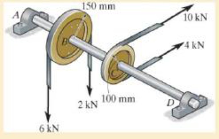
Determine the maximum shear stress in the 40-mm-diameter shaft.
Expert Solution & Answer
Want to see the full answer?
Check out a sample textbook solution
Students have asked these similar questions
A 10-kg box is pulled along P,Na rough surface by a force P, as shown in thefigure. The pulling force linearly increaseswith time, while the particle is motionless att = 0s untilit reaches a maximum force of100 Nattimet = 4s. If the ground has staticand kinetic friction coefficients of u, = 0.6 andHU, = 0.4 respectively, determine the velocityof the
A
1
0
-
kg box is pulled along P
,
N
a rough surface by a force P
,
as shown in the
figure. The pulling force linearly increases
with time, while the particle is motionless at
t
=
0
s untilit reaches a maximum force of
1
0
0
Nattimet
=
4
s
.
If the ground has static
and kinetic friction coefficients of u
,
=
0
.
6
and
HU
,
=
0
.
4
respectively, determine the velocity
of the particle att
=
4
s
.
Calculate the speed of the driven member with the following conditions:
Diameter of the motor pulley: 4 in Diameter of the driven pulley: 12 in Speed of the motor pulley: 1800 rpm
4. In the figure, shaft A made of AISI 1010 hot-rolled steel, is welded to a fixed
support and is subjected to loading by equal and opposite Forces F via shaft B.
Stress concentration factors K₁ (1.7) and Kts (1.6) are induced by the 3mm fillet.
Notch sensitivities are q₁=0.9 and qts=1. The length of shaft A from the fixed
support to the connection at shaft B is 1m. The load F cycles from 0.5 to 2kN and
a static load P is 100N. For shaft A, find the factor of safety (for infinite life) using
the modified Goodman fatigue failure criterion.
3 mm
fillet
Shaft A
20 mm
25 mm
Shaft B
25 mm
Chapter 5 Solutions
Mechanics Of Materials, Si Edition
Ch. 5.3 - Determine the internal torque at each section and...Ch. 5.3 - Determine the. internal torque at each section and...Ch. 5.3 - The solid and hollow shafts are each subjected to...Ch. 5.3 - The motor delivers 10 hp to the shaft. If it...Ch. 5.3 - The solid circular shaft is subjected to an...Ch. 5.3 - The hollow circular shaft is subjected to an...Ch. 5.3 - The shaft is hollow from A to B and solid from B...Ch. 5.3 - Determine the maximum shear stress in the...Ch. 5.3 - Determine the maximum shear stress in the shaft at...Ch. 5.3 - Determine the shear stress a: point A on the...
Ch. 5.3 - The solid 50-mm-diameter shaft is subjected to the...Ch. 5.3 - The gear motor can develop 3 hp when it turns at...Ch. 5.3 - The solid shaft of radius r is subjected to a...Ch. 5.3 - The solid shaft of radius r is subjected to a...Ch. 5.3 - 5-3. The solid shaft is fixed to the support at C...Ch. 5.3 - The copper pipe has an outer diameter of 40 mm and...Ch. 5.3 - The copper pipe has an outer diameter of 2.50 in....Ch. 5.3 - Prob. 5.6PCh. 5.3 - Prob. 5.7PCh. 5.3 - The solid 30-mm-diameter shaft is used to transmit...Ch. 5.3 - The solid shaft is fixed to the support at C and...Ch. 5.3 - Prob. 5.10PCh. 5.3 - The assembly consists of two sections of...Ch. 5.3 - Prob. 5.12PCh. 5.3 - 5-13. If The tubular shaft is made from material...Ch. 5.3 - A steel tube having an outer diameter of 2.5 in....Ch. 5.3 - Prob. 5.15PCh. 5.3 - Prob. 5.16PCh. 5.3 - The rod has a diameter of 1 in. and a weight of 10...Ch. 5.3 - The rod has a diameter of 1 in. and a weight of 15...Ch. 5.3 - 5-19. The shaft consists of solid 80-mm-diameter...Ch. 5.3 - Prob. 5.20PCh. 5.3 - 5-21. If the 40-mm-diameter rod is subjected to a...Ch. 5.3 - Prob. 5.22PCh. 5.3 - Prob. 5.23PCh. 5.3 - Prob. 5.24PCh. 5.3 - Prob. 5.25PCh. 5.3 - Prob. 5.26PCh. 5.3 - Prob. 5.27PCh. 5.3 - Prob. 5.28PCh. 5.3 - Prob. 5.29PCh. 5.3 - Prob. 5.30PCh. 5.3 - The solid steel shaft AC has a diameter of 25 mm...Ch. 5.3 - The pump operates using the motor that has a power...Ch. 5.3 - Prob. 5.33PCh. 5.3 - Prob. 5.34PCh. 5.3 - Prob. 5.35PCh. 5.3 - Prob. 5.36PCh. 5.3 - Prob. 5.37PCh. 5.3 - Prob. 5.38PCh. 5.3 - Prob. 5.39PCh. 5.3 - Prob. 5.40PCh. 5.3 - The A-36 steel tubular shaft is 2 m long and has...Ch. 5.3 - Prob. 5.42PCh. 5.3 - The solid shaft has a linear taper from rA at one...Ch. 5.3 - *5-44. The rod has a diameter of 0.5 in. and...Ch. 5.3 - 5-45. Solve Prob. 5-44 for the maximum torsional...Ch. 5.3 - A motor delivers 500 hp to the shaft, which is...Ch. 5.4 - The 60 mm-diameter steel shaft is subjected to the...Ch. 5.4 - Prob. 5.10FPCh. 5.4 - The hollow 6061-T6 aluminum shaft has an outer and...Ch. 5.4 - A series of gears are mounted on the...Ch. 5.4 - The 80-mm-diameter shaft is made of steel. If it...Ch. 5.4 - The 80-mm-diameter shaft is made of steel. If it...Ch. 5.4 - The propellers of a ship are connected to an A-36...Ch. 5.4 - Show that the maximum shear strain in the shaft is...Ch. 5.4 - 5-49. The A-36 steel axle is made from tubes AB...Ch. 5.4 - Prob. 5.50PCh. 5.4 - Determine the maximum allowable torque T. Also,...Ch. 5.4 - If the allowable shear stress is allow = 80 MPa,...Ch. 5.4 - Prob. 5.53PCh. 5.4 - If gear B supplies 15 kW of power, while gears A,...Ch. 5.4 - If the shaft is made of steel with the allowable...Ch. 5.4 - *5-56. The A-36 steel axle is made from tubes AB...Ch. 5.4 - If the rotation of the 100-mm-diameter A-36 steel...Ch. 5.4 - If the rotation of the 100-mm-diameter A-36 steel...Ch. 5.4 - It has a diameter of 1 in. and is supported by...Ch. 5.4 - Prob. 5.60PCh. 5.4 - Prob. 5.61PCh. 5.4 - Prob. 5.62PCh. 5.4 - Prob. 5.63PCh. 5.4 - Prob. 5.64PCh. 5.4 - Prob. 5.65PCh. 5.4 - When it is rotating at 80 rad/s. it transmits 32...Ch. 5.4 - It is required to transmit 35 kW of power from the...Ch. 5.4 - Prob. 5.68PCh. 5.4 - If a torque of T = 50 N m is applied to the bolt...Ch. 5.4 - If a torque of T= 50N m is applied to the bolt...Ch. 5.4 - Prob. 5.72PCh. 5.4 - If the shaft is subjected to a torque T at its...Ch. 5.4 - Prob. 5.74PCh. 5.4 - Prob. 5.75PCh. 5.4 - *5-76. A cylindrical spring consists of a rubber...Ch. 5.5 - Gst = 75 GPa.Ch. 5.5 - The A992 steel shaft has a diameter of 60 mm and...Ch. 5.5 - If the shaft is fixed at its ends A and B and...Ch. 5.5 - Prob. 5.80PCh. 5.5 - Prob. 5.81PCh. 5.5 - 5-82. The shaft is made from a solid steel section...Ch. 5.5 - 5-83. The motor A develops a torque at gear B of...Ch. 5.5 - If the allowable shear stresses for the magnesium...Ch. 5.5 - If a torque of T = 5 kNm is applied to end A,...Ch. 5.5 - Each has a diameter of 25 mm and they are...Ch. 5.5 - Each has a diameter of 25 mm and they are...Ch. 5.5 - It is fixed at its ends and subjected to a torque...Ch. 5.5 - 5–89. Determine the absolute maximum shear stress...Ch. 5.5 - The shaft is subjected to a torque of 800 lbft....Ch. 5.5 - Prob. 5.91PCh. 5.5 - The shaft is made of 2014-T6 aluminum alloy and is...Ch. 5.5 - The tapered shaft is confined by the fixed...Ch. 5.5 - Determine the reactions at the fixed supports A...Ch. 5.7 - 5-95. The aluminum rod has a square cross section...Ch. 5.7 - Prob. 5.96PCh. 5.7 - Prob. 5.97PCh. 5.7 - If it is subjected to the torsional loading,...Ch. 5.7 - Solve Prob.5-98 for the maximum shear stress...Ch. 5.7 - determine the maximum shear stress in the shaft....Ch. 5.7 - If the shaft has an equilateral triangle cross...Ch. 5.7 - 5-102. The aluminum strut is fixed between the two...Ch. 5.7 - is applied to the tube If the wall thickness is...Ch. 5.7 - If it is 2 m long, determine the maximum shear...Ch. 5.7 - Also, find the angle of twist of end B. The shaft...Ch. 5.7 - Also, find the corresponding angle of twist at end...Ch. 5.7 - If the solid shaft is made from red brass C83400...Ch. 5.7 - If the solid shaft is made from red brass C83400...Ch. 5.7 - The tube is 0.1 in. thick.Ch. 5.7 - 5-110. For a given maximum average shear stress,...Ch. 5.7 - 5-111. A torque T is applied to two tubes having...Ch. 5.7 - By what percentage is the torsional strength...Ch. 5.7 - 5-113. Determine the constant thickness of the...Ch. 5.7 - 5-114. Determine the torque T that can be applied...Ch. 5.7 - If the allowable shear stress is allow = 8 ksi,...Ch. 5.7 - *5-116. The tube is made of plastic, is 5 mm...Ch. 5.7 - 5–117. The mean dimensions of the cross section of...Ch. 5.7 - 5–118. The mean dimensions of the cross section of...Ch. 5.7 - If it is subjected to a torque of T = 40 Nm....Ch. 5.10 - If the transition between the cross sections has a...Ch. 5.10 - 5–121. The step shaft is to be designed to rotate...Ch. 5.10 - Prob. 5.122PCh. 5.10 - 5–123. The transition at the cross sections of the...Ch. 5.10 - *5–124. The steel used for the step shaft has an...Ch. 5.10 - 5–125. The step shaft is subjected to a torque of...Ch. 5.10 - Determine the radius of the elastic core produced...Ch. 5.10 - Assume that the material becomes fully plastic.Ch. 5.10 - diameter is subjected to a torque of 100 in.kip....Ch. 5.10 - Determine the torque T needed to form an elastic...Ch. 5.10 - Determine the torque applied to the shaft.Ch. 5.10 - 5–131. An 80-mm-diameter solid circular shaft is...Ch. 5.10 - Determine the ratio of the plastic torque Tp to...Ch. 5.10 - 5–133. If the step shaft is elastic-plastic as...Ch. 5.10 - 5–134. The solid shaft is made from an...Ch. 5.10 - 5–135. A 1.5-in.-diameter shaft is made from an...Ch. 5.10 - *5–136. The tubular shaft is made of a...Ch. 5.10 - 5–137. The shaft is made from a strain-hardening...Ch. 5.10 - 5–138. The tube is made of elastic-perfectly...Ch. 5.10 - Determine the torque required to cause a maximum...Ch. 5.10 - *5–140. The 2-m-long tube is made of an...Ch. 5.10 - is made from an elastic perfectly plastic material...Ch. 5.10 - 5–142. The 2-m-long lube is made from an...Ch. 5 - The shaft is made of A992 steel and has an...Ch. 5 - The shaft is made of A992 steel and has an...Ch. 5 - Determine the shear stress at the mean radius p =...Ch. 5 - If the thickness of its 2014-T6-aluminum skin is...Ch. 5 - Determine which shaft geometry will resist the...Ch. 5 - If couple forces P = 3 kip are applied to the...Ch. 5 - If the allowable shear stress for the aluminum is...Ch. 5 - Determine the angle of twist of its end A if it is...Ch. 5 - This motion is caused by the unequal belt tensions...
Knowledge Booster


Learn more about
Need a deep-dive on the concept behind this application? Look no further. Learn more about this topic, mechanical-engineering and related others by exploring similar questions and additional content below.Similar questions
- Please sovle this for me and please don't use aiarrow_forwardPlease sovle this for me and please don't use aiarrow_forward3. The cold-drawn AISI 1040 steel bar shown in the figure is subjected to a completely reversed axial load fluctuating between 28 kN in compression to 28 kN in tension. Estimate the fatigue factor of safety based on achieving infinite life (using Goodman line) and the yielding factor of safety. If infinite life is not predicted, estimate the number of cycles to failure. 25 mm + 6-mm D. 10 mmarrow_forward
- CORRECT AND DETAILED SOLUTION WITH FBD ONLY. I WILL UPVOTE 1. The truss shown is supported by hinge at A and cable at E.Given: H = 4m, S = 1.5 m, α = 75⁰, θ = 33⁰.Allowable tensile stress in cable = 64 MPa.Allowable compressive stress in all members = 120 MPaAllowable tensile stress in all members = 180 MPa1.Calculate the maximum permissible P, in kN, if the diameter of the cable is 20 mm.2.If P = 40 kN, calculate the required area (mm2) of member BC.3. If members have solid square section, with dimension 15 mm, calculate the maximum permissible P (kN) based on the allowable strength of member HI.ANSWERS: (1) 45.6 kN; (2) 83.71 mm2; (3) 171.76 kNarrow_forwardCORRECT AND DETAILED SOLUTION WITH FBD ONLY. I WILL UPVOTE 2: A wire 4 meters long is stretched horizontally between points 4 meters apart. The wire is 25 mm2 in cross-section with a modulus of elasticity of 200 GPa. A load W placed at the center of the wire produces a sag Δ.1.Calculate the tension (N) in the wire if sag Δ = 30 mm.2.Calculate the magnitude of W, in N, if sag Δ = 54.3 mm.3. If W is 60 N, what is the sag (in mm)?ANSWERS: (1) 562 N, (2) 100 N, (3) 45.8 Narrow_forwardCORRECT AND DETAILED SOLUTION WITH FBD ONLY. I WILL UPVOTE 4 : A cable and pulley system at D is used to bring a 230-kg pole (ACB) to a vertical position as shown. The cable has tensile force T and is attached at C. The length of the pole is 6.0 m, the outer diameter is d = 140 mm, and the wall thickness t = 12 mm. The pole pivots about a pin at A. The allowable shear stress in the pin is 60 MPa and the allowable bearing stress is 90 MPa. The diameter of the cable is 8 mm.1.Find the minimum diameter (mm) of the pin at A to support the weight of the pole in the position shown.2.Calculate the elongation (mm) of the cable CD.3.Calculate the vertical displacement of point C, in mm.ANSWERS: (1) 6 mm, (2) 1.186 mm, (3) 1.337 mm--arrow_forward
- 1. Derive an expression for H(w) filter or bandpass/reject filter. = for the circuit below. Qualitatively determine if it's a high/lowpass L ell R ww Voarrow_forward2. Obtain the transfer function, H(w) = 0 for the circuit below for R₁ = 1 kQ2, R2 = 10 kQ, and Vi C = 1 μF. What role, if any, does the capacitor play? Explain. R₁ R2 + C + Voarrow_forwardCORRECT AND DETAILED SOLUTION WITH FBD ONLY. I WILL UPVOTE 3 (15 points): A 12-meter-long precast pile segment is to be lifted from a trailer down to the ground and then set in place prior to driving by a crane.1. If two slings are to be used in lifting the pile to the ground, at what distance from the ends must the slings be placed for minimum bending due to its own weight?2. At what distance from the ends must the slings be placed for minimum shear due to its own weight?3. Using one sling to set the pile in a vertical position before driving at what distance from one end must the sling be placed for minimum bending due to its own weight?ANSWERS: (1) 2.48 m, (2) 3.00 m, (3) 3.51 marrow_forward
arrow_back_ios
SEE MORE QUESTIONS
arrow_forward_ios
Recommended textbooks for you
 Elements Of ElectromagneticsMechanical EngineeringISBN:9780190698614Author:Sadiku, Matthew N. O.Publisher:Oxford University Press
 Mechanics of Materials (10th Edition)Mechanical EngineeringISBN:9780134319650Author:Russell C. HibbelerPublisher:PEARSON
 Thermodynamics: An Engineering ApproachMechanical EngineeringISBN:9781259822674Author:Yunus A. Cengel Dr., Michael A. BolesPublisher:McGraw-Hill Education
 Control Systems EngineeringMechanical EngineeringISBN:9781118170519Author:Norman S. NisePublisher:WILEY
 Mechanics of Materials (MindTap Course List)Mechanical EngineeringISBN:9781337093347Author:Barry J. Goodno, James M. GerePublisher:Cengage Learning
 Engineering Mechanics: StaticsMechanical EngineeringISBN:9781118807330Author:James L. Meriam, L. G. Kraige, J. N. BoltonPublisher:WILEY
Elements Of Electromagnetics
Mechanical Engineering
ISBN:9780190698614
Author:Sadiku, Matthew N. O.
Publisher:Oxford University Press
Mechanics of Materials (10th Edition)
Mechanical Engineering
ISBN:9780134319650
Author:Russell C. Hibbeler
Publisher:PEARSON
Thermodynamics: An Engineering Approach
Mechanical Engineering
ISBN:9781259822674
Author:Yunus A. Cengel Dr., Michael A. Boles
Publisher:McGraw-Hill Education
Control Systems Engineering
Mechanical Engineering
ISBN:9781118170519
Author:Norman S. Nise
Publisher:WILEY
Mechanics of Materials (MindTap Course List)
Mechanical Engineering
ISBN:9781337093347
Author:Barry J. Goodno, James M. Gere
Publisher:Cengage Learning
Engineering Mechanics: Statics
Mechanical Engineering
ISBN:9781118807330
Author:James L. Meriam, L. G. Kraige, J. N. Bolton
Publisher:WILEY
Everything About COMBINED LOADING in 10 Minutes! Mechanics of Materials; Author: Less Boring Lectures;https://www.youtube.com/watch?v=N-PlI900hSg;License: Standard youtube license