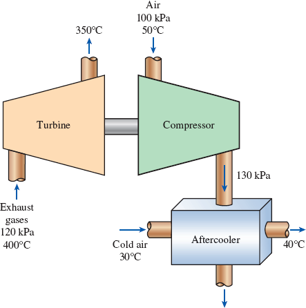
The turbocharger of an internal combustion engine consists of a turbine and a compressor. Hot exhaust gases flow through the turbine to produce work, and the work output from the turbine is used as the work input to the compressor. The pressure of ambient air is increased as it flows through the compressor before it enters the engine cylinders. Thus, the purpose of a turbocharger is to increase the pressure of air so that more air gets into the cylinder. Consequently, more fuel can be burned and more power can be produced by the engine.
In a turbocharger, exhaust gases enter the turbine at 400°C and 120 kPa at a rate of 0.02 kg/s and leave at 350°C. Air enters the compressor at 50°C and 100 kPa and leaves at 130 kPa at a rate of 0.018 kg/s. The compressor increases the air pressure with a side effect: It also increases the air temperature, which increases the possibility that a gasoline engine will experience an engine knock. To avoid this, an aftercooler is placed after the compressor to cool the warm air with cold ambient air before it enters the engine cylinders. It is estimated that the aftercooler must decrease the air temperature below 80°C if knock is to be avoided. The cold ambient air enters the aftercooler at 30°C and leaves at 40°C. Disregarding any frictional losses in the turbine and the compressor and treating the exhaust gases as air, determine (a) the temperature of the air at the compressor outlet and (b) the minimum volume flow rate of ambient air required to avoid knock.
FIGURE P5–188

(a)
The temperature of the air at the compressor outlet.
Answer to Problem 187RP
The temperature of the air at the compressor outlet is
Explanation of Solution
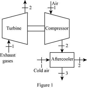
Draw the schematic diagram of the given turbo charger of the engine as shown in
Figure 1.

Write the general energy rate balance equation.
Here, the rate of heat transfer is
The system is at steady state. Hence, the rate of change in net energy of the system becomes zero.
Refer Figure 1 and Refer Equation (I).
For turbine:
Consider the turbine is adiabatic, neglect the heat transfer. Also neglect the kinetic and potential energy changes. The work done is by the system (turbine) and the work done on the system is zero i.e.
The Equations (I) reduced as follows to obtain the work output of compressor.
The change in enthalpy is expressed as follow.
Here, the specific heat of exhaust gas is
Substitute
For compressor:
Consider the compressor is adiabatic, neglect the heat transfer. Also neglect the kinetic and potential energy changes. The work done is on the system (compressor) and the work done by the system is zero i.e.
The Equations (I) reduced as follows to obtain the work input of compressor.
Here, the mass flow rate is
Refer Table A-2(b), “Ideal-gas specific heats of various common gases”.
The specific heat at constant pressure
The specific heat at constant pressure
The specific heat at constant pressure
Conclusion:
Substitute
Here,
Substitute
Thus, the temperature of the air at the compressor outlet is
(b)
The minimum volume flow rate of ambient air required to avoid knock.
Answer to Problem 187RP
The minimum volume flow rate of ambient air required to avoid knock is
Explanation of Solution
Refer Figure 1 and Refer Equation (I).
For aftercooler:
The after cooler is the two inlet and two outlet system.
Refer the Equation (I) Express the energy rate balance equation for aftercooler as follows
Here, subscript
Write the formula for volume flow rate of cold air.
Here, the gas constant of air is
Refer Table A-1, “Molar mass, gas constant, and critical-point properties”.
The gas constant
Conclusion:
Substitute,
Substitute
Thus, the minimum volume flow rate of ambient air required to avoid knock is
Want to see more full solutions like this?
Chapter 5 Solutions
THERMODYNAMICS(SI UNITS,INTL.ED)EBOOK>I
- 2. Steam enters a turbine stage with an enthalpy of 3628 kJ/kg at 74 m/s and leaves the same stage with an enthalpy of 2846 kJ/kg and a velocity of 400 ft/s. Calculate the work done by the steam.arrow_forward2. Steam enters a turbine stage with an enthalpy of 3628 kJ/kg at 70 m/s and leave the same stage with an enthalpy of 2846 kj/kg and a velocity of 124 m/s. Calculate the work done by the steam.arrow_forward3. Steam enters the turbine at the rate of 1.5 kg/s with enthalpy of 2300 kJ/kg and exhaust enthalpy of 1200 kJ/kg. Steam is extracted from the turbine at a rate of 0.87 kg/s for heating purposes with enthalpy of 2570 kJ/kg. What is the turbine work, in HP?arrow_forward
- Assume all the processes to be reversible and the heat losses from the pump and the turbine to be negligible. (a) If steam enters a pump (operates between the pressure limits of 5 MPa and 10 kPa) as saturated liquid, determine the pump work (consumed) per unit mass. (b) If steam leaves a turbine (operates between the pressure limits of 5 MPa and 10 kPa) as saturated vapor, determine the turbine work (delivered) per unit mass.arrow_forward3. Steam enters the turbine at the rate of 1.5 kg/s with enthalpy of 2300 kJ/kg and exhaust enthalpy of 1200 kJ/kg. Steam is extracted from the turbine at a rate of 0.87 kg/s for heating purposes with enthalpy of 2570 kJ/kg. What is the turbine work, in HP?arrow_forward12 kg of air per minute is delivered by a centrifugal air compressor It enters the compressor at a velocity of 12 m/s with a pressure of 1 bar and specific volume of 0. 5 m/kg and leaves at a velocity of 90 m/s with a pressure of 8 bar and specific volume of 0.14 m/kg. The increase in enthalpy of air passing through the compressor is (h-hi = 150 kJ/kg) and heat loos to the surroundings at a rate of 700 kJ/min. Assume the inlet and discharge line are at the same level. Answer the following; a. What are the main assumptions b. Calculate the power required to drive the compressor, in kW! c. Calculate the ratio of inlet and outlet pipe diameter? Air out Boundary Centrifugal compressor di Air inarrow_forward
- In a jet engine, the emitter, compressor, turbine and nozzle operate at isentropic pressure, while the combustion chamber operates at constant pressure. At the inlet of the emitter, the temperature of the air is 230 K, the pressure is 25 kPa, the flow rate is 30 kg/s and the speed is 200 m/s. Since the pressure of the air at the compressor outlet is 500 kPa, the temperature of the air at the turbine inlet is 1000 K and the pressure of the air at the nozzle outlet is 25 kPa,a) Draw the flow diagram of the cycle schematically.b) Find the velocity of the gases at the nozzle exit.c) Find the amount of heat supplied to the combustion chamber.d) Find the reaction force, reaction force and reaction efficiency.arrow_forwardA pump-turbine is a piece of equipment that can operate either as a pump or as a turbine, depending on the direction of the water flow. The picture on the right shows a pump-turbine system.When it is daytime, this system is used as a turbine, taking water from the upper reservoir and discharging it into the lower reservoir, producing electricity. When it is nighttime, electricity is cheaper, and this system is used as a pump, taking water from the lower reservoir and discharging it into the higher reservoir, so that it can produce electricity again the next day when it is used as a turbine. Consider that, using the system as a turbine or pump, the water flow is 1m3/s and the pressure drop is 5 m, determine:(a) The power extracted from the fluid by the turbine (points 1 and 2 are as shown in the figure: z1=35 m and z2=0 m).(b) The useful power delivered to the fluid by the pump (points 1 and 2 in the figure should be reversed: z1=0 m and z2=35 m).arrow_forwardA gas turbine unit has a maximum cycle temperature of 800°C and pressure 12MPa. Calculate the network output in kW of an electric generator geared to the turbine when the air enters the compressor at 20°C temperature and 4MPa pressure. The air flows through the gas power unit at the rate of 123kg/min.arrow_forward
- (b) The entropy of the steam increases in actual steam turbines as a result of irreversibilities. In an effort to control entropy increase, it is proposed to cool the steam in the turbine by running cooling water around the turbine casing. It is argued that this will reduce the entropy and the enthalpy of the steam at the turbine exit and this increase the work output. Evaluate this proposal.arrow_forward9. A turbine receives steam at 2778.1 kl/kg enthalpy and then converts it to shaft work. The steam leaves the turbine with 1200 kJ/kg enthalpy. Assuming no losses due to gravity, heat, and friction, determine the power produced in kW if 5 kg/s of steam flows at the inletarrow_forward4. Steam enters the condenser of a steam power plant at 20000 kPa and a quality of 95 percent with a mass flow rate of 20 Mg/h. It is to be cooled by water from a nearby river in circulating the water through the tubes within the condenser. To prevent thermal pollution, the river water is not allowed to experience a temperature rise above 10oC. If the steam is to leave the condenser as saturated liquid at 20000 Pa, determine the mass flow rate of the cooling water requiredarrow_forward
 Elements Of ElectromagneticsMechanical EngineeringISBN:9780190698614Author:Sadiku, Matthew N. O.Publisher:Oxford University Press
 Mechanics of Materials (10th Edition)Mechanical EngineeringISBN:9780134319650Author:Russell C. HibbelerPublisher:PEARSON
 Thermodynamics: An Engineering ApproachMechanical EngineeringISBN:9781259822674Author:Yunus A. Cengel Dr., Michael A. BolesPublisher:McGraw-Hill Education
 Control Systems EngineeringMechanical EngineeringISBN:9781118170519Author:Norman S. NisePublisher:WILEY
 Mechanics of Materials (MindTap Course List)Mechanical EngineeringISBN:9781337093347Author:Barry J. Goodno, James M. GerePublisher:Cengage Learning
 Engineering Mechanics: StaticsMechanical EngineeringISBN:9781118807330Author:James L. Meriam, L. G. Kraige, J. N. BoltonPublisher:WILEY


