
Videos
A tank with an internal volume of 1 m3 contains air at 800 kPa and 25°C. A valve on the tank is opened, allowing air to escape, and the pressure inside quickly drops to 150 kPa, at which point the valve is closed. Assume there is negligible heat transfer from the tank to the air left in the tank.
- (a) Using the approximation he ≈ constant = he,avg = 0.5 (h1 + h2), calculate the mass withdrawn during the process.
- (b) Consider the same process but broken into two parts. That is, consider an intermediate state at P2 = 400 kPa, calculate the mass removed during the process from P1 = 800 kPa to P2 and then the mass removed during the process from P2 to P3 = 150 kPa, using the type of approximation used in part (a), and add the two to get the total mass removed.
- (c) Calculate the mass removed if the variation of he is accounted for.
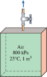
FIGURE P5–185
(a)
The mass withdrawn during the process.
Answer to Problem 177RP
The mass withdrawn during the process is
Explanation of Solution
Write the equation of mass balance.
Here, the inlet mass is
The change in mass of the system for the control volume is expressed as,
Here, the suffixes 1 and 2 indicates the initial and final states of the system.
Consider the tank as the control volume. Initially the tank is filled with air and the valve is in closed position, further no other mass is allowed to enter the tank. Hence, the inlet mass is neglected i.e.
Rewrite the Equation (I) as follows.
Write the formula for initial and final mass of air present in the tank.
Here, the mass of air is
Write the energy balance equation.
Here, the heat transfer is
When the valve is opened and air starts escape from the tank. Neglect the heat transfer and work done i.e.
The Equation (V) reduced as follows.
The enthalpy and internal energy in terms of temperature and specific heats are expressed as follows.
Rewrite the Equation (VI) as follows.
The temperature of the air while exiting the tank is considered as the average temperature of initial and final temperatures.
Refer Table A-1, “Molar mass, gas constant, and critical-point properties”.
The gas constant
Refer Table A-2b, “Ideal-gas specific heats of various common gases”.
The specific heat at constant pressure
Conclusion:
Substitute
Substitute
Substitute
Use Engineering Equation Solver (EES) or online calculator to solve the Equation (VIII) and obtain the value of
Substitute
Substitute
Thus, the mass withdrawn during the process is
(b)
The mass withdrawn during the pressure reduced from
Answer to Problem 177RP
The total mass withdrawn during the process 1-3 is
Explanation of Solution
Consider Process 1-2:
The pressure drop from
Substitute
Substitute
Substitute
Use Engineering Equation Solver (EES) or online calculator to solve the Equation (IX) and obtain the value of
Substitute
Substitute
Thus, the mass withdrawn during the process 1-2 is
Consider Process 2-3:
The pressure drop from
Here,
Substitute
Substitute
Substitute
Use Engineering Equation Solver (EES) or online calculator to solve the Equation (X) and obtain the value of
Substitute
Substitute
Thus, the mass withdrawn during the process 2-3 is
The total mass withdrawn during the process 1-3 is as follows.
Thus, the total mass withdrawn during the process 1-3 is
(c)
The mass withdrawn during the process if there is variation in
Answer to Problem 177RP
The mass withdrawn during the process is
Explanation of Solution
Write the general mass balance equation.
Here, the inlet mass flow rate is
Refer Equation (XI).
Write the mass balance equation for the given system.
Rewrite the Equation (XII) as follows.
Write the general energy rate balance equation.
Here, the rate of total energy in is
The system is at steady state. Hence, the rate of change in net energy of the system becomes zero.
Refer Equation (XIII).
Write the energy balance equation for the given system.
Here, the mass is
Substitute
The enthalpy and internal energy is expressed as follows.
Substitute
The mass of air in terms ideal gas is expressed as follows.
Rewrite the Equation (XVI) as follows.
Using
Substitute
Here,
Integrate the Equation (XVIII) at the initial-1 and final-2 states.
Refer Table A-2(a), “Ideal-gas specific heats of various common gases”.
The specific heat ratio
Conclusion:
Substitute
Substitute
Substitute
Thus, the mass withdrawn during the process is
Want to see more full solutions like this?
Chapter 5 Solutions
THERMODYNAMICS(SI UNITS,INTL.ED)EBOOK>I
Additional Engineering Textbook Solutions
Fluid Mechanics: Fundamentals and Applications
Starting Out with C++ from Control Structures to Objects (9th Edition)
Management Information Systems: Managing The Digital Firm (16th Edition)
Automotive Technology: Principles, Diagnosis, And Service (6th Edition) (halderman Automotive Series)
Java: An Introduction to Problem Solving and Programming (8th Edition)
Starting Out with Programming Logic and Design (5th Edition) (What's New in Computer Science)


- Can you provide steps and an explaination on how the height value to calculate the Pressure at point B is (-5-3.5) and the solution is 86.4kPa.arrow_forwardPROBLEM 3.46 The solid cylindrical rod BC of length L = 600 mm is attached to the rigid lever AB of length a = 380 mm and to the support at C. When a 500 N force P is applied at A, design specifications require that the displacement of A not exceed 25 mm when a 500 N force P is applied at A For the material indicated determine the required diameter of the rod. Aluminium: Tall = 65 MPa, G = 27 GPa. Aarrow_forwardFind the equivalent mass of the rocker arm assembly with respect to the x coordinate. k₁ mi m2 k₁arrow_forward
- 2. Figure below shows a U-tube manometer open at both ends and containing a column of liquid mercury of length l and specific weight y. Considering a small displacement x of the manometer meniscus from its equilibrium position (or datum), determine the equivalent spring constant associated with the restoring force. Datum Area, Aarrow_forward1. The consequences of a head-on collision of two automobiles can be studied by considering the impact of the automobile on a barrier, as shown in figure below. Construct a mathematical model (i.e., draw the diagram) by considering the masses of the automobile body, engine, transmission, and suspension and the elasticity of the bumpers, radiator, sheet metal body, driveline, and engine mounts.arrow_forward3.) 15.40 – Collar B moves up at constant velocity vB = 1.5 m/s. Rod AB has length = 1.2 m. The incline is at angle = 25°. Compute an expression for the angular velocity of rod AB, ė and the velocity of end A of the rod (✓✓) as a function of v₂,1,0,0. Then compute numerical answers for ȧ & y_ with 0 = 50°.arrow_forward
- 2.) 15.12 The assembly shown consists of the straight rod ABC which passes through and is welded to the grectangular plate DEFH. The assembly rotates about the axis AC with a constant angular velocity of 9 rad/s. Knowing that the motion when viewed from C is counterclockwise, determine the velocity and acceleration of corner F.arrow_forward500 Q3: The attachment shown in Fig.3 is made of 1040 HR. The static force is 30 kN. Specify the weldment (give the pattern, electrode number, type of weld, length of weld, and leg size). Fig. 3 All dimension in mm 30 kN 100 (10 Marks)arrow_forward(read image) (answer given)arrow_forward
- A cylinder and a disk are used as pulleys, as shown in the figure. Using the data given in the figure, if a body of mass m = 3 kg is released from rest after falling a height h 1.5 m, find: a) The velocity of the body. b) The angular velocity of the disk. c) The number of revolutions the cylinder has made. T₁ F Rd = 0.2 m md = 2 kg T T₂1 Rc = 0.4 m mc = 5 kg ☐ m = 3 kgarrow_forward(read image) (answer given)arrow_forward11-5. Compute all the dimensional changes for the steel bar when subjected to the loads shown. The proportional limit of the steel is 230 MPa. 265 kN 100 mm 600 kN 25 mm thickness X Z 600 kN 450 mm E=207×103 MPa; μ= 0.25 265 kNarrow_forward
 Elements Of ElectromagneticsMechanical EngineeringISBN:9780190698614Author:Sadiku, Matthew N. O.Publisher:Oxford University Press
 Mechanics of Materials (10th Edition)Mechanical EngineeringISBN:9780134319650Author:Russell C. HibbelerPublisher:PEARSON
 Thermodynamics: An Engineering ApproachMechanical EngineeringISBN:9781259822674Author:Yunus A. Cengel Dr., Michael A. BolesPublisher:McGraw-Hill Education
 Control Systems EngineeringMechanical EngineeringISBN:9781118170519Author:Norman S. NisePublisher:WILEY
 Mechanics of Materials (MindTap Course List)Mechanical EngineeringISBN:9781337093347Author:Barry J. Goodno, James M. GerePublisher:Cengage Learning
 Engineering Mechanics: StaticsMechanical EngineeringISBN:9781118807330Author:James L. Meriam, L. G. Kraige, J. N. BoltonPublisher:WILEY