
Engineering Mechanics: Statics
13th Edition
ISBN: 9780132915540
Author: Russell C. Hibbeler
Publisher: Prentice Hall
expand_more
expand_more
format_list_bulleted
Videos
Textbook Question
Chapter 5.4, Problem 61P
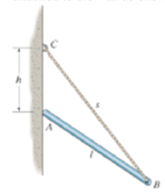
The uniform rod has a length I and weight W. It is supported at one end A by a smooth wall and the other end by a cord of length s which is attached to the wall as shown. Determine the placement h for equilibrium.
Prob. 5-55
Expert Solution & Answer
Want to see the full answer?
Check out a sample textbook solution
Students have asked these similar questions
Please solve this problem as soon as possible My ID# 016948724
The gears shown in the figure have a diametral pitch of 2 teeth per inch and a 20° pressure angle.
The pinion rotates at 1800 rev/min clockwise and transmits 200 hp through the idler pair to gear
5 on shaft c. What forces do gears 3 and 4 transmit to the idler shaft?
TS
I
y
18T
32T
This
a
12
x
18T
C
48T
5
Question 1. Draw 3 teeth for the following pinion and gear respectively. The teeth
should be drawn near the pressure line so that the teeth from the pinion should
mesh those of the gear. Drawing scale (1:1). Either a precise hand drawing or
CAD drawing is acceptable. Draw all the trajectories of the involute lines and the
circles.
Specification: 18tooth pinion and 30tooth gear. Diameter pitch=P=6 teeth /inch.
Pressure angle:20°, 1/P for addendum (a) and 1.25/P for dedendum (b). For fillet,
c=b-a.
Chapter 5 Solutions
Engineering Mechanics: Statics
Ch. 5.2 - Prob. 1PCh. 5.2 - Prob. 2PCh. 5.2 - Prob. 3PCh. 5.2 - Prob. 4PCh. 5.2 - Prob. 5PCh. 5.2 - Prob. 6PCh. 5.2 - Prob. 7PCh. 5.2 - Prob. 8PCh. 5.2 - Prob. 9PCh. 5.4 - Determine the horizontal and vertical components...
Ch. 5.4 - Determine the horizontal and vertical components...Ch. 5.4 - The truss is supported by a pin at A and a roller...Ch. 5.4 - Determine the components of reaction at the fixed...Ch. 5.4 - The 25 kg bar has a center of mass at G. If it is...Ch. 5.4 - Determine the reactions at the smooth contact...Ch. 5.4 - Determine the horizontal and vertical components...Ch. 5.4 - Prob. 11PCh. 5.4 - Determine the components of the support reactions...Ch. 5.4 - Prob. 13PCh. 5.4 - Prob. 14PCh. 5.4 - Determine the horizontal and vertical components...Ch. 5.4 - Determine the components of reaction at the...Ch. 5.4 - Prob. 17PCh. 5.4 - Determine the tension in the cable and the...Ch. 5.4 - Prob. 19PCh. 5.4 - Prob. 20PCh. 5.4 - Prob. 21PCh. 5.4 - Prob. 22PCh. 5.4 - Prob. 23PCh. 5.4 - Prob. 24PCh. 5.4 - Determine the magnitude of force at the pin A and...Ch. 5.4 - Prob. 26PCh. 5.4 - Prob. 27PCh. 5.4 - Prob. 28PCh. 5.4 - Prob. 29PCh. 5.4 - Prob. 30PCh. 5.4 - Prob. 31PCh. 5.4 - Prob. 32PCh. 5.4 - Prob. 33PCh. 5.4 - Prob. 34PCh. 5.4 - Prob. 35PCh. 5.4 - Prob. 36PCh. 5.4 - The boom supports the two vertical loads. Neglect...Ch. 5.4 - The boom is intended to support two vertical loads...Ch. 5.4 - Prob. 39PCh. 5.4 - Prob. 40PCh. 5.4 - Prob. 41PCh. 5.4 - The cantilevered jib crane is used to support the...Ch. 5.4 - The cantilevered jib crane is used to support the...Ch. 5.4 - Prob. 44PCh. 5.4 - Prob. 45PCh. 5.4 - Three uniform books each having a weight W and...Ch. 5.4 - Prob. 47PCh. 5.4 - Prob. 48PCh. 5.4 - Prob. 49PCh. 5.4 - Prob. 50PCh. 5.4 - Prob. 51PCh. 5.4 - A boy stands out at the end of the diving board,...Ch. 5.4 - The uniform beam has a weight Wand length l and is...Ch. 5.4 - Determine the distance d for placement of the load...Ch. 5.4 - If d = 1 m, and = 30, determine me normal...Ch. 5.4 - Prob. 56PCh. 5.4 - Assuming that the foundation exerts a linearly...Ch. 5.4 - Assuming that the foundation exerts a linearly...Ch. 5.4 - Prob. 59PCh. 5.4 - The 30-N uniform rod has a length of l = 1 m. If s...Ch. 5.4 - The uniform rod has a length I and weight W. It is...Ch. 5.7 - The uniform plate has a weight of 500 lb....Ch. 5.7 - Determine the reactions at the roller support A,...Ch. 5.7 - The rod is supported by smooth journal bearings at...Ch. 5.7 - Determine the support reactions at the smooth...Ch. 5.7 - Determine the force developed in the short link...Ch. 5.7 - Determine the components of reaction that the...Ch. 5.7 - Determine the tension each rope and the force that...Ch. 5.7 - Determine the vertical reactions at the wheels C...Ch. 5.7 - Prob. 64PCh. 5.7 - If these components have weights WA = 45000 Wa =...Ch. 5.7 - Prob. 66PCh. 5.7 - Prob. 67PCh. 5.7 - Prob. 68PCh. 5.7 - Prob. 69PCh. 5.7 - Determine the components of reaction at hinges A...Ch. 5.7 - Prob. 71PCh. 5.7 - Prob. 72PCh. 5.7 - Prob. 73PCh. 5.7 - Prob. 74PCh. 5.7 - Prob. 75PCh. 5.7 - Prob. 76PCh. 5.7 - Determine the horizontal equilibrium force P that...Ch. 5.7 - Determine the components of reaction at A and the...Ch. 5.7 - Compute the x, y, z components of reaction at the...Ch. 5.7 - Determine the magnitude of F2 which will cause the...Ch. 5.7 - Determine the x, y, z components of reaction at...Ch. 5.7 - Prob. 82PCh. 5.7 - Determine the horizontal tension T in the belt on...Ch. 5.7 - Determine the horizontal tension T in the belt on...Ch. 5.7 - If the roller at 8 can sustain a maximum load of 3...Ch. 5.7 - Determine the normal reaction at the roller A and...Ch. 5.7 - Prob. 87RPCh. 5.7 - Prob. 88RPCh. 5.7 - I he uniform rod of length L and weight W is...Ch. 5.7 - Determine the x, y, z components of reaction at...Ch. 5.7 - Determine the x, y, z components of reaction at...Ch. 5.7 - Determine the reactions at the supports A and B...
Knowledge Booster


Learn more about
Need a deep-dive on the concept behind this application? Look no further. Learn more about this topic, mechanical-engineering and related others by exploring similar questions and additional content below.Similar questions
- 5. The figure shows a gear train. There is no friction at the bearings except for the gear tooth forces. The material of the milled gears is steel having a Brinell hardness of 170. The input shaft speed (n2) is 800 rpm. The face width and the contact angle for all gears are 1 in and 20° respectively. In this gear set, the endurance limit (Se) is 15 kpsi and nd (design factor) is 2. (a) Find the revolution speed of gear 5. (b) Determine whether each gear satisfies the design factor of 2.0 for bending fatigue. (c) Determine whether each gear satisfies the design factor of 2.0 for surface fatigue (contact stress). (d) According to the computation results of the questions (b) and (c), explain the possible failure mechanisms for each gear. N4=28 800rpm N₁=43 N5=34 N₂=14 P(diameteral pitch)=8 for all gears Coupled to 2.5hp motorarrow_forward1. The rotating steel shaft is simply supported by bearings at points of B and C, and is driven by a spur gear at D, which has a 6-in pitch diameter. The force F from the drive gear acts at a pressure angle of 20°. The shaft transmits a torque to point A of TA =3000 lbĘ in. The shaft is machined from steel with Sy=60kpsi and Sut=80 kpsi. (1) Draw a shear force diagram and a bending moment diagram by F. According to your analysis, where is the point of interest to evaluate the safety factor among A, B, C, and D? Describe the reason. (Hint: To find F, the torque Tд is generated by the tangential force of F (i.e. Ftangential-Fcos20°) When n=2.5, K=1.8, and K₁ =1.3, determine the diameter of the shaft based on (2) static analysis using DE theory (note that fatigue stress concentration factors need to be used for this question because the loading condition is fatigue) and (3) a fatigue analysis using modified Goodman. Note) A standard diameter is not required for the questions. 10 in Darrow_forward3 N2=28 P(diametral pitch)=8 for all gears Coupled to 25 hp motor N3=34 Full depth spur gears with pressure angle=20° N₂=2000 rpm (1) Compute the circular pitch, the center-to-center distance, and base circle radii. (2) Draw the free body diagram of gear 3 and show all the forces and the torque. (3) In mounting gears, the center-to-center distance was reduced by 0.1 inch. Calculate the new values of center-to-center distance, pressure angle, base circle radii, and pitch circle diameters. (4)What is the new tangential and radial forces for gear 3? (5) Under the new center to center distance, is the contact ratio (mc) increasing or decreasing?arrow_forward
- 2. A flat belt drive consists of two 4-ft diameter cast-iron pulleys spaced 16 ft apart. A power of 60 hp is transmitted by a pulley whose speed is 380 rev/min. Use a service factor (Ks) pf 1.1 and a design factor 1.0. The width of the polyamide A-3 belt is 6 in. Use CD=1. Answer the following questions. (1) What is the total length of the belt according to the given geometry? (2) Find the centrifugal force (Fc) applied to the belt. (3) What is the transmitted torque through the pulley system given 60hp? (4) Using the allowable tension, find the force (F₁) on the tight side. What is the tension at the loose side (F2) and the initial tension (F.)? (5) Using the forces, estimate the developed friction coefficient (f) (6) Based on the forces and the given rotational speed, rate the pulley set. In other words, what is the horse power that can be transmitted by the pulley system? (7) To reduce the applied tension on the tight side, the friction coefficient is increased to 0.75. Find out the…arrow_forwardThe tooth numbers for the gear train illustrated are N₂ = 24, N3 = 18, №4 = 30, №6 = 36, and N₁ = 54. Gear 7 is fixed. If shaft b is turned through 5 revolutions, how many turns will shaft a make? a 5 [6] barrow_forwardCE-112 please solve this problem step by step and give me the correct answerarrow_forward
- CE-112 please solve this problem step by step and give me the correct answerarrow_forwardCE-112 solve this problem step by step and give me the correct answer pleasearrow_forwardPlease do not use any AI tools to solve this question. I need a fully manual, step-by-step solution with clear explanations, as if it were done by a human tutor. No AI-generated responses, please.arrow_forward
- Please do not use any AI tools to solve this question. I need a fully manual, step-by-step solution with clear explanations, as if it were done by a human tutor. No AI-generated responses, please.arrow_forwardCE-112 please solve this problem step by step and give me the correct answerarrow_forwardCE-112 please solve this problem step by step and give me the correct asnwerarrow_forward
arrow_back_ios
SEE MORE QUESTIONS
arrow_forward_ios
Recommended textbooks for you
 International Edition---engineering Mechanics: St...Mechanical EngineeringISBN:9781305501607Author:Andrew Pytel And Jaan KiusalaasPublisher:CENGAGE L
International Edition---engineering Mechanics: St...
Mechanical Engineering
ISBN:9781305501607
Author:Andrew Pytel And Jaan Kiusalaas
Publisher:CENGAGE L
Mechanical SPRING DESIGN Strategy and Restrictions in Under 15 Minutes!; Author: Less Boring Lectures;https://www.youtube.com/watch?v=dsWQrzfQt3s;License: Standard Youtube License