
Vector Mechanics for Engineers: Statics
12th Edition
ISBN: 9781259977244
Author: BEER
Publisher: MCG
expand_more
expand_more
format_list_bulleted
Concept explainers
Videos
Textbook Question
Chapter 5.3, Problem 5.70P
5.68 through 5.73 Determine the reactions at the beam supports for the given loading.
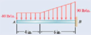
Fig. P5.68
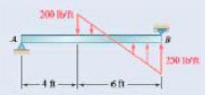
Fig. P5.70
Expert Solution & Answer
Want to see the full answer?
Check out a sample textbook solution
Students have asked these similar questions
A man skis down a slope. His initial elevation was 150 m and his velocity at the bottom of the slope is 17 m/s. What percentage of his initial potential energy was consumed due to friction and air resistance? Use the accounting equation in your calculations.
In direct calorimetry, a person is placed in a large, water-insulated chamber. The chamber is kept at a constant temperature. While in the chamber, the subject is asked to perform a number of normal activities, such as eating, sleeping, and exercising. The rate of heat released from the subject’s body can be measured by the rate of heat gain by the water bath. Would direct calorimetry be a practical way to measure metabolic rate? Why or why not?A person is placed inside a calorimetric chamber for 24 hours. During this time, the 660-gallon water bath heats up by 3.2°F. What is the subject’s metabolic rate during this period? Report your answer in kcal/day. Assume that there is no heat loss from the water to the surroundings.
Upon reentry into the Earth’s atmosphere, the bottom of a space shuttle heats up to dangerous levels as the craft slows for landing. If the velocity of the shuttle is 28,500 km/hr at the beginning of reentry and 370 km/hr just prior to landing, how much energy is lost as heat? The shuttle has a mass of 90,000 kg. Assume that the change in potential energy is negligible compared to the change in kinetic energy.
Chapter 5 Solutions
Vector Mechanics for Engineers: Statics
Ch. 5.1 - 5.1 through 5.9 Locate the centroid of the plane...Ch. 5.1 - Locate the centroid of the plane area shown.Ch. 5.1 - Locate the centroid of the plane area shown.Ch. 5.1 - Locate the centroid of the plane area shown.Ch. 5.1 - Locate the centroid of the plane area shown.Ch. 5.1 - Locate the centroid of the plane area shown.Ch. 5.1 - Locate the centroid of the plane area shown.Ch. 5.1 - Locate the centroid of the plane area shown.Ch. 5.1 - Locate the centroid of the plane area shown.Ch. 5.1 - Locate the centroid of the plane area shown.
Ch. 5.1 - Locate the centroid of the plane area shown.Ch. 5.1 - Locate the centroid of the plane area shown.Ch. 5.1 - Locate the centroid of the plane area shown.Ch. 5.1 - Locate the centroid of the plane area shown.Ch. 5.1 - Locate the centroid of the plane area shown.Ch. 5.1 - PROBLEM 5.16 Determine the y coordinate of the...Ch. 5.1 - Show that as r1 approaches r2, the location of the...Ch. 5.1 - For the area shown, determine the ratio a/b for...Ch. 5.1 - For the semiannular area of Prob. 5.12, determine...Ch. 5.1 - A built-up beam is constructed by nailing seven...Ch. 5.1 - The horizontal x axis is drawn through the...Ch. 5.1 - The horizontal x-axis is drawn through the...Ch. 5.1 - PROBLEM 5.23 The first moment of the shaded area...Ch. 5.1 - A thin, homogeneous wire is bent to form the...Ch. 5.1 - A thin, homogeneous wire is bent to form the...Ch. 5.1 - A thin, homogeneous wire is bent to form the...Ch. 5.1 - A thin, homogeneous wire is bent to form the...Ch. 5.1 - The homogeneous wire ABC is bent into a...Ch. 5.1 - The frame for a sign is fabricated from thin, flat...Ch. 5.1 - The homogeneous wire ABCD is bent as shown and is...Ch. 5.1 - The homogeneous wire ABCD is bent as shown and is...Ch. 5.1 - Determine the distance h for which the centroid of...Ch. 5.1 - Knowing that the distance h has been selected to...Ch. 5.2 - Determine by direct integration the centroid of...Ch. 5.2 - 5.34 through 5.36 Determine by direct integration...Ch. 5.2 - 5.34 through 5.36 Determine by direct integration...Ch. 5.2 - 5.37 through 5.39 Determine by direct integration...Ch. 5.2 - 5.37 through 5.39 Determine by direct integration...Ch. 5.2 - 5.37 through 5.39 Determine by direct integration...Ch. 5.2 - 5.40 and 5.41 Determine by direct integration the...Ch. 5.2 - 5.40 and 5.41 Determine by direct integration the...Ch. 5.2 - Determine by direct integration the centroid of...Ch. 5.2 - 5.43 and 5.44 Determine by direct integration the...Ch. 5.2 - 5.43 and 5.44 Determine by direct integration the...Ch. 5.2 - 5.45 and 5.46 A homogeneous wire is bent into the...Ch. 5.2 - 5.45 and 5.46 A homogeneous wire is bent into the...Ch. 5.2 - A homogeneous wire is bent into the shape shown....Ch. 5.2 - 5.48 and 5.49 Determine by direct integration the...Ch. 5.2 - 5.48 and 5.49 Determine by direct integration the...Ch. 5.2 - Determine the centroid of the area shown in terms...Ch. 5.2 - Determine the centroid of the area shown when a =...Ch. 5.2 - Determine the volume and the surface area of the...Ch. 5.2 - Determine the volume and the surface area of the...Ch. 5.2 - Determine the volume and the surface area of the...Ch. 5.2 - Determine the volume and the surface area of the...Ch. 5.2 - Determine the volume of the solid generated by...Ch. 5.2 - Verify that the expressions for the volumes of the...Ch. 5.2 - Knowing that two equal caps have been removed from...Ch. 5.2 - Three different drive belt profiles are to be...Ch. 5.2 - Determine the capacity, in liters, of the punch...Ch. 5.2 - Determine the volume and total surface area of the...Ch. 5.2 - Determine the volume and weight of the solid brass...Ch. 5.2 - Determine the total surface area of the solid...Ch. 5.2 - Determine the volume of the brass collar obtained...Ch. 5.2 - The shade for a wall-mounted light is formed from...Ch. 5.3 - 5.66 and 5.67 For the beam and loading shown,...Ch. 5.3 - 5.66 and 5.67 For the beam and loading shown,...Ch. 5.3 - 5.68 through 5.73 Determine the reactions at the...Ch. 5.3 - 5.68 through Determine the reactions at the beam...Ch. 5.3 - 5.68 through 5.73 Determine the reactions at the...Ch. 5.3 - 5.68 through Determine the reactions at the beam...Ch. 5.3 - 5.68 through 5.73 Determine the reactions at the...Ch. 5.3 - 5.68 through 5.73 Determine the reactions at the...Ch. 5.3 - Determine (a) the distance a so that the vertical...Ch. 5.3 - Determine (a) the distance a so that the reaction...Ch. 5.3 - Determine the reactions at the beam supports for...Ch. 5.3 - Determine (a) the distributed load w0 at the end D...Ch. 5.3 - The beam AB supports two concentrated loads and...Ch. 5.3 - For the beam and loading of Prob. 5.78, determine...Ch. 5.3 - The cross section of a concrete dam is as shown....Ch. 5.3 - The cross section of a concrete dam is as shown....Ch. 5.3 - The dam for a lake is designed to withstand the...Ch. 5.3 - The base of a dam for a lake is designed to resist...Ch. 5.3 - Prob. 5.84PCh. 5.3 - Prob. 5.85PCh. 5.3 - The 3 4-m side AB of a tank is hinged at its...Ch. 5.3 - The 3 4-m side of an open tank is hinged at its...Ch. 5.3 - A 0.5 0.8-m gate AB is located at the bottom of a...Ch. 5.3 - A 0.5 0.8-m gate AB is located at the bottom of a...Ch. 5.3 - A 4 2-ft gate is hinged at A and is held in...Ch. 5.3 - Fig. P5.90 5.91 Solve Prob. 5.90 if the gate...Ch. 5.3 - A prismatically shaped gate placed at the end of a...Ch. 5.3 - A prismatically shaped gate placed at the end of a...Ch. 5.3 - A long trough is supported by a continuous hinge...Ch. 5.3 - The square gate AB is held in the position shown...Ch. 5.4 - Consider the composite body shown. Determine (a)...Ch. 5.4 - A cone and a cylinder of the same radius a and...Ch. 5.4 - Determine the location of the center of gravity of...Ch. 5.4 - Prob. 5.99PCh. 5.4 - For the stop bracket shown, locate the x...Ch. 5.4 - Fig. P5.100 and P5.101 5.101 For the stop bracket...Ch. 5.4 - Prob. 5.102PCh. 5.4 - Prob. 5.103PCh. 5.4 - For the machine element shown, locate the y...Ch. 5.4 - For the machine element shown, locate the x...Ch. 5.4 - 5.106 and 5.107 Locate the center of gravity of...Ch. 5.4 - 5.106 and 5.107 Locate the center of gravity of...Ch. 5.4 - A corner reflector for tracking by radar has two...Ch. 5.4 - A wastebasket, designed to fit in the corner of a...Ch. 5.4 - An elbow for the duct of a ventilating system is...Ch. 5.4 - A window awning is fabricated from sheet metal...Ch. 5.4 - Locate the center of gravity of the sheet-metal...Ch. 5.4 - Locate the center of gravity of the sheet-metal...Ch. 5.4 - A thin steel wire with a uniform cross section is...Ch. 5.4 - The frame of a greenhouse is constructed from...Ch. 5.4 - Locate the center of gravity of the figure shown,...Ch. 5.4 - Prob. 5.117PCh. 5.4 - A scratch awl has a plastic handle and a steel...Ch. 5.4 - PROBLEM 5.117 A bronze bushing is mounted inside a...Ch. 5.4 - PROBLEM 5.120 A brass collar, of length 2.5 in.,...Ch. 5.4 - PROBLEM 5.121 The three legs of a small...Ch. 5.4 - Prob. 5.122PCh. 5.4 - Determine by direct integration the values of x...Ch. 5.4 - Prob. 5.124PCh. 5.4 - PROBLEM 5.125 Locate the centroid of the volume...Ch. 5.4 - Prob. 5.126PCh. 5.4 - Prob. 5.127PCh. 5.4 - PROBLEM 5.128 Locate the centroid of the volume...Ch. 5.4 - PROBLEM 5.129 Locate the centroid of the volume...Ch. 5.4 - Show that for a regular pyramid of height h and n...Ch. 5.4 - PROBLEM 5.131 Determine by direct integration the...Ch. 5.4 - PROBLEM 5.132 The sides and the base of a punch...Ch. 5.4 - Locate the centroid of the section shown, which...Ch. 5.4 - Locate the centroid of the section shown, which...Ch. 5.4 - Determine by direct integration the location of...Ch. 5.4 - Alter grading a lot, a builder places four stakes...Ch. 5 - 5.137 and 5.138 Locate the centroid of the plane...Ch. 5 - 5.137 and 5.138 Locate the centroid of the plane...Ch. 5 - Prob. 5.139RPCh. 5 - Determine by direct integration the centroid of...Ch. 5 - Determine by direct integration the centroid of...Ch. 5 - The escutcheon (a decorative plate placed on a...Ch. 5 - Determine the reactions at the supports for the...Ch. 5 - A beam is subjected to a linearly distributed...Ch. 5 - A tank is divided into two sections by a 1 1-m...Ch. 5 - Determine the y coordinate of the centroid of the...Ch. 5 - An 8-in.-diameter cylindrical duct and a 4 8-in....Ch. 5 - Three brass plates are brazed to a steel pipe to...
Knowledge Booster


Learn more about
Need a deep-dive on the concept behind this application? Look no further. Learn more about this topic, mechanical-engineering and related others by exploring similar questions and additional content below.Similar questions
- of the basket of the balloon at point A, and their other ends are staked to the ground. The hook is located in the geometric center of the basket. The balloon and the air inside it have a combined mass of 3000 kg. You want to determine the resultant of the tension forces in the four cables acting on the hook at point A. It is known that the magnitudes of the tension in the cables are as follows: TAB = 207 N; TAC = 355 N; TAD = 250 N; and TAE = 486 N. B E 2.5 m C E 5.5 m D 2.5 m 3.5 m 1.5 m Using the information provided in the problem, express the force on the hook at point A by cable AC in rectangular component form. The force on the hook at point A by cable AC in rectangular component form is given below. T AC N) i+ N) + N) Rarrow_forwardWater in the glass tube is at a temperature of 40°C. Plot the height of the water as a function of the tube's inner diameter D for 0.5mm≤D≤3mm. Use increments of 0.5mm. Take sigma=69.6mN/m, and theta=0° for the contact angle.arrow_forwardDetermine the distance h that the column of mercury in the tube will be depressed when the tube is inserted into the mercury at a room temperature of 68 F. Plot this relationship of h (vertical axis) versus D for 0.5 in≤D≤0.150in. Give values for increments of ΔD=0.025in. Discuss this resultarrow_forward
- Water is at a temperature of 30 C. Plot the height h of the water as a function of the gap w between the two glass plates for 0.4 mm ≤ w ≤ 2.4 mm. Use increments of 0.4mm. Take sigma=0.0718 N/m.arrow_forwardWhat is the reading on the vernier calipers? 7 6 0 5 10 8arrow_forwardDetermine the moments of the force about the x and the a axes. O 4 m F = {-40i +20j + 10k} N 3 m 6 m aarrow_forward
- 6. A part of the structure for a factory automation system is a beam that spans 30.0 in as shown in Figure P5-6. Loads are applied at two points, each 8.0 in from a support. The left load F₁ = 1800 lb remains constantly applied, while the right load F₂ = 1800 lb is applied and removed fre- quently as the machine cycles. Evaluate the beam at both B and C. A 8 in F₁ = 1800 lb 14 in F2 = 1800 lb 8 in D RA B C 4X2X1/4 Steel tube Beam cross section RDarrow_forward30. Repeat Problem 28, except using a shaft that is rotating and transmitting a torque of 150 N⚫m from the left bear- ing to the middle of the shaft. Also, there is a profile key- seat at the middle under the load.arrow_forward28. The shaft shown in Figure P5-28 is supported by bear- ings at each end, which have bores of 20.0 mm. Design the shaft to carry the given load if it is steady and the shaft is stationary. Make the dimension a as large as pos- sible while keeping the stress safe. Determine the required d = 20mm D = ? R = ?| 5.4 kN d=20mm Length not to scale -a = ?- +а= a = ? + -125 mm- -250 mm- FIGURE P5-28 (Problems 28, 29, and 30)arrow_forward
- 12. Compute the estimated actual endurance limit for SAE 4130 WQT 1300 steel bar with a rectangular cross sec- tion of 20.0 mm by 60 mm. It is to be machined and subjected to repeated and reversed bending stress. A reli- ability of 99% is desired.arrow_forward28. The shaft shown in Figure P5-28 is supported by bear- ings at each end, which have bores of 20.0 mm. Design the shaft to carry the given load if it is steady and the shaft is stationary. Make the dimension a as large as pos- sible while keeping the stress safe. Determine the required d = 20mm D = ? R = ?| 5.4 kN d=20mm Length not to scale -a = ?- +а= a = ? + -125 mm- -250 mm- FIGURE P5-28 (Problems 28, 29, and 30)arrow_forward2. A strut in a space frame has a rectangular cross section of 10.0 mm by 30.0 mm. It sees a load that varies from a tensile force of 20.0 kN to a compressive force of 8.0 kN.arrow_forward
arrow_back_ios
SEE MORE QUESTIONS
arrow_forward_ios
Recommended textbooks for you
 Elements Of ElectromagneticsMechanical EngineeringISBN:9780190698614Author:Sadiku, Matthew N. O.Publisher:Oxford University Press
 Mechanics of Materials (10th Edition)Mechanical EngineeringISBN:9780134319650Author:Russell C. HibbelerPublisher:PEARSON
 Thermodynamics: An Engineering ApproachMechanical EngineeringISBN:9781259822674Author:Yunus A. Cengel Dr., Michael A. BolesPublisher:McGraw-Hill Education
 Control Systems EngineeringMechanical EngineeringISBN:9781118170519Author:Norman S. NisePublisher:WILEY
 Mechanics of Materials (MindTap Course List)Mechanical EngineeringISBN:9781337093347Author:Barry J. Goodno, James M. GerePublisher:Cengage Learning
 Engineering Mechanics: StaticsMechanical EngineeringISBN:9781118807330Author:James L. Meriam, L. G. Kraige, J. N. BoltonPublisher:WILEY
Elements Of Electromagnetics
Mechanical Engineering
ISBN:9780190698614
Author:Sadiku, Matthew N. O.
Publisher:Oxford University Press
Mechanics of Materials (10th Edition)
Mechanical Engineering
ISBN:9780134319650
Author:Russell C. Hibbeler
Publisher:PEARSON
Thermodynamics: An Engineering Approach
Mechanical Engineering
ISBN:9781259822674
Author:Yunus A. Cengel Dr., Michael A. Boles
Publisher:McGraw-Hill Education
Control Systems Engineering
Mechanical Engineering
ISBN:9781118170519
Author:Norman S. Nise
Publisher:WILEY
Mechanics of Materials (MindTap Course List)
Mechanical Engineering
ISBN:9781337093347
Author:Barry J. Goodno, James M. Gere
Publisher:Cengage Learning
Engineering Mechanics: Statics
Mechanical Engineering
ISBN:9781118807330
Author:James L. Meriam, L. G. Kraige, J. N. Bolton
Publisher:WILEY
Types Of loads - Engineering Mechanics | Abhishek Explained; Author: Prime Course;https://www.youtube.com/watch?v=4JVoL9wb5yM;License: Standard YouTube License, CC-BY