
Vector Mechanics for Engineers: Statics
12th Edition
ISBN: 9781259977244
Author: BEER
Publisher: MCG
expand_more
expand_more
format_list_bulleted
Concept explainers
Videos
Textbook Question
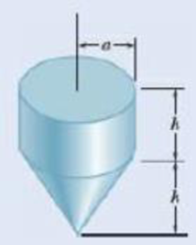
Chapter 5.4, Problem 5.97P
A cone and a cylinder of the same radius a and height h are attached as shown. Determine the location of the centroid of the composite body.
Expert Solution & Answer
Want to see the full answer?
Check out a sample textbook solution
Students have asked these similar questions
A triangular distributed load of max intensity w acts on beam
AB. The beam is supported by a pin at A and member CD,
which is connected by pins at C and D respectively.
Determine the largest load intensity, Wmax, that can be
applied if the pin at D can support a maximum force of
18000 N. Also determine the reactions at A and C
and express each answer in Cartesian components. Assume
the masses of both beam and member ✓ are
negligible.
Dwas
шал
=
A
BY NC SA
2016 Eric Davishahl
C
D
-a-
Ур
-b-
X
B
W
Values for dimensions on the figure are given in the following
table. Note the figure may not be to scale.
Variable Value
a
6.6 m
b
11.88 m
C
4.29 m
The maximum load intensity is
=
wmax
N/m.
The reaction at A is A =
The reaction at C is
=
i+
Ĵ N.
ĴN.
12
i+
The beam is supported by a pin at B and a roller at C and is
subjected to the loading shown with w =110 lb/ft, and F
205 lb.
a.) If M
=
2,590 ft-lb, determine the support reactions at B
and C. Report your answers in both Cartesian components.
b.) Determine the largest magnitude of the applied couple M
for which the beam is still properly supported in equilibrium
with the pin and roller as shown.
2013 Michael Swanbom
CC
BY NC SA
M
ру
W
B⚫
C
F
ka
b
Values for dimensions on the figure are given in the following
table. Note the figure may not be to scale.
Variable Value
a
3.2 ft
b
6.4 ft
C
3 ft
a.) The reaction at B is B =
The reaction at C is C =
ĵ lb.
i+
Ĵ lb.
b.) The largest couple that can be applied is M
ft-lb.
==
i+
The beam ABC has a mass of 79.0 kg and is supported by
the rope BDC that runs through the frictionless pulley at D
. The winch at C has a mass of 36.5 kg. The tension in the
rope acts on the beam at points B and C and counteracts
the moments due to the beam's weight (acting vertically at
the midpoint of its length) and the weight of the winch
(acting vertically at point C) such that the resultant moment
about point A is equal to zero. Assume that rope segment
CD is vertical and note that rope segment BD is NOT
necessarily perpendicular to the beam.
a.) Compute the tension in the rope.
b.) Model the two forces the rope exerts on the beam as a
single equivalent force and couple moment acting at point B.
Enter your answer in Cartesian components.
c.) Model the two forces the rope exerts on the beam as a
single equivalent force (no couple) and determine the
distance from A to the point along the beam where the
equivalent force acts (measured parallel to the beam from A
). Enter your answer…
Chapter 5 Solutions
Vector Mechanics for Engineers: Statics
Ch. 5.1 - 5.1 through 5.9 Locate the centroid of the plane...Ch. 5.1 - Locate the centroid of the plane area shown.Ch. 5.1 - Locate the centroid of the plane area shown.Ch. 5.1 - Locate the centroid of the plane area shown.Ch. 5.1 - Locate the centroid of the plane area shown.Ch. 5.1 - Locate the centroid of the plane area shown.Ch. 5.1 - Locate the centroid of the plane area shown.Ch. 5.1 - Locate the centroid of the plane area shown.Ch. 5.1 - Locate the centroid of the plane area shown.Ch. 5.1 - Locate the centroid of the plane area shown.
Ch. 5.1 - Locate the centroid of the plane area shown.Ch. 5.1 - Locate the centroid of the plane area shown.Ch. 5.1 - Locate the centroid of the plane area shown.Ch. 5.1 - Locate the centroid of the plane area shown.Ch. 5.1 - Locate the centroid of the plane area shown.Ch. 5.1 - PROBLEM 5.16 Determine the y coordinate of the...Ch. 5.1 - Show that as r1 approaches r2, the location of the...Ch. 5.1 - For the area shown, determine the ratio a/b for...Ch. 5.1 - For the semiannular area of Prob. 5.12, determine...Ch. 5.1 - A built-up beam is constructed by nailing seven...Ch. 5.1 - The horizontal x axis is drawn through the...Ch. 5.1 - The horizontal x-axis is drawn through the...Ch. 5.1 - PROBLEM 5.23 The first moment of the shaded area...Ch. 5.1 - A thin, homogeneous wire is bent to form the...Ch. 5.1 - A thin, homogeneous wire is bent to form the...Ch. 5.1 - A thin, homogeneous wire is bent to form the...Ch. 5.1 - A thin, homogeneous wire is bent to form the...Ch. 5.1 - The homogeneous wire ABC is bent into a...Ch. 5.1 - The frame for a sign is fabricated from thin, flat...Ch. 5.1 - The homogeneous wire ABCD is bent as shown and is...Ch. 5.1 - The homogeneous wire ABCD is bent as shown and is...Ch. 5.1 - Determine the distance h for which the centroid of...Ch. 5.1 - Knowing that the distance h has been selected to...Ch. 5.2 - Determine by direct integration the centroid of...Ch. 5.2 - 5.34 through 5.36 Determine by direct integration...Ch. 5.2 - 5.34 through 5.36 Determine by direct integration...Ch. 5.2 - 5.37 through 5.39 Determine by direct integration...Ch. 5.2 - 5.37 through 5.39 Determine by direct integration...Ch. 5.2 - 5.37 through 5.39 Determine by direct integration...Ch. 5.2 - 5.40 and 5.41 Determine by direct integration the...Ch. 5.2 - 5.40 and 5.41 Determine by direct integration the...Ch. 5.2 - Determine by direct integration the centroid of...Ch. 5.2 - 5.43 and 5.44 Determine by direct integration the...Ch. 5.2 - 5.43 and 5.44 Determine by direct integration the...Ch. 5.2 - 5.45 and 5.46 A homogeneous wire is bent into the...Ch. 5.2 - 5.45 and 5.46 A homogeneous wire is bent into the...Ch. 5.2 - A homogeneous wire is bent into the shape shown....Ch. 5.2 - 5.48 and 5.49 Determine by direct integration the...Ch. 5.2 - 5.48 and 5.49 Determine by direct integration the...Ch. 5.2 - Determine the centroid of the area shown in terms...Ch. 5.2 - Determine the centroid of the area shown when a =...Ch. 5.2 - Determine the volume and the surface area of the...Ch. 5.2 - Determine the volume and the surface area of the...Ch. 5.2 - Determine the volume and the surface area of the...Ch. 5.2 - Determine the volume and the surface area of the...Ch. 5.2 - Determine the volume of the solid generated by...Ch. 5.2 - Verify that the expressions for the volumes of the...Ch. 5.2 - Knowing that two equal caps have been removed from...Ch. 5.2 - Three different drive belt profiles are to be...Ch. 5.2 - Determine the capacity, in liters, of the punch...Ch. 5.2 - Determine the volume and total surface area of the...Ch. 5.2 - Determine the volume and weight of the solid brass...Ch. 5.2 - Determine the total surface area of the solid...Ch. 5.2 - Determine the volume of the brass collar obtained...Ch. 5.2 - The shade for a wall-mounted light is formed from...Ch. 5.3 - 5.66 and 5.67 For the beam and loading shown,...Ch. 5.3 - 5.66 and 5.67 For the beam and loading shown,...Ch. 5.3 - 5.68 through 5.73 Determine the reactions at the...Ch. 5.3 - 5.68 through Determine the reactions at the beam...Ch. 5.3 - 5.68 through 5.73 Determine the reactions at the...Ch. 5.3 - 5.68 through Determine the reactions at the beam...Ch. 5.3 - 5.68 through 5.73 Determine the reactions at the...Ch. 5.3 - 5.68 through 5.73 Determine the reactions at the...Ch. 5.3 - Determine (a) the distance a so that the vertical...Ch. 5.3 - Determine (a) the distance a so that the reaction...Ch. 5.3 - Determine the reactions at the beam supports for...Ch. 5.3 - Determine (a) the distributed load w0 at the end D...Ch. 5.3 - The beam AB supports two concentrated loads and...Ch. 5.3 - For the beam and loading of Prob. 5.78, determine...Ch. 5.3 - The cross section of a concrete dam is as shown....Ch. 5.3 - The cross section of a concrete dam is as shown....Ch. 5.3 - The dam for a lake is designed to withstand the...Ch. 5.3 - The base of a dam for a lake is designed to resist...Ch. 5.3 - Prob. 5.84PCh. 5.3 - Prob. 5.85PCh. 5.3 - The 3 4-m side AB of a tank is hinged at its...Ch. 5.3 - The 3 4-m side of an open tank is hinged at its...Ch. 5.3 - A 0.5 0.8-m gate AB is located at the bottom of a...Ch. 5.3 - A 0.5 0.8-m gate AB is located at the bottom of a...Ch. 5.3 - A 4 2-ft gate is hinged at A and is held in...Ch. 5.3 - Fig. P5.90 5.91 Solve Prob. 5.90 if the gate...Ch. 5.3 - A prismatically shaped gate placed at the end of a...Ch. 5.3 - A prismatically shaped gate placed at the end of a...Ch. 5.3 - A long trough is supported by a continuous hinge...Ch. 5.3 - The square gate AB is held in the position shown...Ch. 5.4 - Consider the composite body shown. Determine (a)...Ch. 5.4 - A cone and a cylinder of the same radius a and...Ch. 5.4 - Determine the location of the center of gravity of...Ch. 5.4 - Prob. 5.99PCh. 5.4 - For the stop bracket shown, locate the x...Ch. 5.4 - Fig. P5.100 and P5.101 5.101 For the stop bracket...Ch. 5.4 - Prob. 5.102PCh. 5.4 - Prob. 5.103PCh. 5.4 - For the machine element shown, locate the y...Ch. 5.4 - For the machine element shown, locate the x...Ch. 5.4 - 5.106 and 5.107 Locate the center of gravity of...Ch. 5.4 - 5.106 and 5.107 Locate the center of gravity of...Ch. 5.4 - A corner reflector for tracking by radar has two...Ch. 5.4 - A wastebasket, designed to fit in the corner of a...Ch. 5.4 - An elbow for the duct of a ventilating system is...Ch. 5.4 - A window awning is fabricated from sheet metal...Ch. 5.4 - Locate the center of gravity of the sheet-metal...Ch. 5.4 - Locate the center of gravity of the sheet-metal...Ch. 5.4 - A thin steel wire with a uniform cross section is...Ch. 5.4 - The frame of a greenhouse is constructed from...Ch. 5.4 - Locate the center of gravity of the figure shown,...Ch. 5.4 - Prob. 5.117PCh. 5.4 - A scratch awl has a plastic handle and a steel...Ch. 5.4 - PROBLEM 5.117 A bronze bushing is mounted inside a...Ch. 5.4 - PROBLEM 5.120 A brass collar, of length 2.5 in.,...Ch. 5.4 - PROBLEM 5.121 The three legs of a small...Ch. 5.4 - Prob. 5.122PCh. 5.4 - Determine by direct integration the values of x...Ch. 5.4 - Prob. 5.124PCh. 5.4 - PROBLEM 5.125 Locate the centroid of the volume...Ch. 5.4 - Prob. 5.126PCh. 5.4 - Prob. 5.127PCh. 5.4 - PROBLEM 5.128 Locate the centroid of the volume...Ch. 5.4 - PROBLEM 5.129 Locate the centroid of the volume...Ch. 5.4 - Show that for a regular pyramid of height h and n...Ch. 5.4 - PROBLEM 5.131 Determine by direct integration the...Ch. 5.4 - PROBLEM 5.132 The sides and the base of a punch...Ch. 5.4 - Locate the centroid of the section shown, which...Ch. 5.4 - Locate the centroid of the section shown, which...Ch. 5.4 - Determine by direct integration the location of...Ch. 5.4 - Alter grading a lot, a builder places four stakes...Ch. 5 - 5.137 and 5.138 Locate the centroid of the plane...Ch. 5 - 5.137 and 5.138 Locate the centroid of the plane...Ch. 5 - Prob. 5.139RPCh. 5 - Determine by direct integration the centroid of...Ch. 5 - Determine by direct integration the centroid of...Ch. 5 - The escutcheon (a decorative plate placed on a...Ch. 5 - Determine the reactions at the supports for the...Ch. 5 - A beam is subjected to a linearly distributed...Ch. 5 - A tank is divided into two sections by a 1 1-m...Ch. 5 - Determine the y coordinate of the centroid of the...Ch. 5 - An 8-in.-diameter cylindrical duct and a 4 8-in....Ch. 5 - Three brass plates are brazed to a steel pipe to...
Knowledge Booster


Learn more about
Need a deep-dive on the concept behind this application? Look no further. Learn more about this topic, mechanical-engineering and related others by exploring similar questions and additional content below.Similar questions
- w1 Three distributed loads act on a beam as shown. The load between A and B increases linearly from 0 to a maximum intensity of w₁ = 12.8 lb/ft at point B. The load then varies linearly with a different slope to an intensity of w₂ = 17.1 lb/ft at C. The load intensity in section CD of the beam is constant at w3 10.2 lb/ft. For each load region, determine the resultant force and the location of its line of action (distance to the right of A for all cases). cc 10 BY NC SA 2016 Eric Davishahl = WI W2 W3 -b- C Values for dimensions on the figure are given in the following table. Note the figure may not be to scale. Variable Value a 4.50 ft b 5.85 ft с 4.28 ft The resultant load in region AB is FR₁ = lb and acts ft to the right of A. The resultant load in region BC is FR2 lb and acts = ft to the right of A. The resultant load in region CD is FR3 = lb and acts ft to the right of A.arrow_forwardThe T-shaped structure is embedded in a concrete wall at A and subjected to the force F₁ and the force-couple system F2 1650 N and M = 1,800 N-m at the locations shown. Neglect the weight of the structure in your calculations for this problem. = a.) Compute the allowable range of magnitudes for F₁ in the direction shown if the connection at A will fail when subjected to a resultant moment with a magnitude of 920 N- m or higher. b.) Focusing on the forces and igonoring given M for now. Using the value for F1, min that you calculated in (a), replace the two forces F₁ and F2 with a single force that has equivalent effect on the structure. Specify the equivalent →> force Feq in Cartesian components and indicate the horizontal distance from point A to its line of action (note this line of action may not intersect the structure). c.) Now, model the entire force system (F1,min, F2, and M) as a single force and couple acting at the junction of the horizontal and vertical sections of the…arrow_forwardThe heated rod from Problem 3 is subject to a volumetric heating h(x) = h0 x L in units of [Wm−3], as shown in the figure below. Under the heat supply the temperature of the rod changes along x with the temperature function T (x). The temperature T (x) is governed by the d following equations: − dx (q(x)) + h(x) = 0 PDE q(x) =−k dT dx Fourier’s law of heat conduction (4) where q(x) is the heat flux through the rod and k is the (constant) thermal conductivity. Both ends of the bar are in contact with a heat reservoir at zero temperature. Determine: 1. Appropriate BCs for this physical problem. 2. The temperature function T (x). 3. The heat flux function q(x). Side Note: Please see that both ends of bar are in contact with a heat reservoir at zero temperature so the boundary condition at the right cannot be du/dx=0 because its not thermally insulated. Thank youarrow_forward
- The elastic bar from Problem 1 spins with angular velocity ω about an axis, as shown in the figure below. The radial acceleration at a generic point x along the bar is a(x) = ω2x. Under this radial acceleration, the bar stretches along x with displacement function u(x). The displacement d u(x) is governed by the following equations: dx (σ(x)) + ρa(x) = 0 PDE σ(x) = E du dx Hooke’s law (2) where σ(x) is the axial stress in the rod, ρ is the mass density, and E is the (constant) Young’s modulus. The bar is pinned on the rotation axis at x = 0 and it is also pinned at x = L. Determine: 1. Appropriate BCs for this physical problem. 2. The displacement function u(x). 3. The stress function σ(x). SIDE QUESTION: I saw a tutor solve it before but I didn't understand why the tutor did not divide E under the second term (c1x) before finding u(x). The tutor only divided E under first term. please explain and thank youarrow_forwardcalculate the total power required to go 80 mph in a VW Type 2 Samba Bus weighing 2310 lbs. with a Cd of 0.35 and a frontal area of 30ft^2. Consider the coefficient of rolling resistance to be 0.018. What is the increase in power required to go the same speed if the weight is increased by 2205 pounds (the rated carrying capacity of the vehicle). If the rated power for the vehicle is 49 bhp, will the van be able to reach 80 mph at full carrying capacity?arrow_forwardA distillation column with a total of 13 actual stages (including a partial condenser) is used to perform a separation which requires 7 ideal stages. Calculate the overall column efficiency, and report your answer in %arrow_forward
- 6. Consider a 10N step input to the mechanical system shown below, take M = 15kg, K = 135N/m, and b = 0.4 Ns/m. (a) Assume zero initial condition, calculate the (i) System pole (ii) System characterization, and (iii) The time domain response (b) Calculate the steady-state value of the system b [ www K 个 х M -F(+)arrow_forward2. Solve the following linear time invariant differential equations using Laplace transforms subject to different initial conditions (a) y-y=t for y(0) = 1 and y(0) = 1 (b) ÿ+4y+ 4y = u(t) for y(0) = 0 and y(0) = 1 (c) y-y-2y=0 for y(0) = 1 and y(0) = 0arrow_forward3. For the mechanical systems shown below, the springs are undeflected when x₁ = x2 = x3 = 0 and the input is given as fa(t). Draw the free-body diagrams and write the modeling equations governing each of the systems. K₁ 000 K₂ 000 M₁ M2 -fa(t) B₂ B₁ (a) fa(t) M2 K₂ 000 B K₁ x1 000 M₁ (b)arrow_forward
- This question i m uploading second time . before you provide me incorrect answer. read the question carefully and solve accordily.arrow_forward1. Create a table comparing five different analogous variables for translational, rotational, electrical and fluid systems. Include the standard symbols for each variable in their respective systems.arrow_forward2) Suppose that two unequal masses m₁ and m₂ are moving with initial velocities v₁ and v₂, respectively. The masses hit each other and have a coefficient of restitution e. After the impact, mass 1 and 2 head to their respective gaps at angles a and ẞ, respectively. Derive expressions for each of the angles in terms of the initial velocities and the coefficient of restitution. m1 m2 8 m1 m2 βarrow_forward
arrow_back_ios
SEE MORE QUESTIONS
arrow_forward_ios
Recommended textbooks for you
 International Edition---engineering Mechanics: St...Mechanical EngineeringISBN:9781305501607Author:Andrew Pytel And Jaan KiusalaasPublisher:CENGAGE L
International Edition---engineering Mechanics: St...
Mechanical Engineering
ISBN:9781305501607
Author:Andrew Pytel And Jaan Kiusalaas
Publisher:CENGAGE L
Mechanical Engineering: Centroids & Center of Gravity (1 of 35) What is Center of Gravity?; Author: Michel van Biezen;https://www.youtube.com/watch?v=Tkyk-G1rDQg;License: Standard Youtube License