
Concept explainers
(a)
Maximum permissible load using LFRD method.
Answer to Problem 5.5.1P
The maximum permissible load from LFRD method is
Explanation of Solution
Given information:
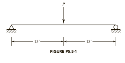
A W 10X 77 has continuous lateral support. The load P is a service live load and
Following is the given beam:

Calculation:
We have following properties for W 10X 77 from ASIC manual
| DesignationImperial (in x lb/ft) | Depth h (in) | Width w (in) | Web Thickness tw (in) | Flange Thickness tf (in) | Sectional Area (in2) | Weight (lbf/ft) | Static Parameters | ||||
| Moment of Inertia | Elastic Section Modulus | ||||||||||
| Ix (in4) | Iy (in4) | Sx (in3) | Sy (in3) | ||||||||
| W 10 x 77 | 10.60 | 10.190 | 0.530 | 0.870 | 22.6 | 77 | 455 | 154 | 85.9 | 30.1 | |
Let’s check for the compactness of the given W-shape beam using part
For Flange:
Where,
If the above condition satisfies, then the flange is non compact for flexure
Therefore, the web is compact.
Calculate the nominal flexural strength using the formula
Where,
Manual.
Now, calculate the maximum bending moment due to dead load, we have
Maximum bending moment for a simply supported beam carrying a dead UDL
Where,
Substitute,
Calculate the maximum bending moment for a simply supported beam carrying a concentrated
live load of the beam:
Where, P is the concentrated load and L is the length of the beam is.
Now, using Load Resistance and Factored design method:
Calculate the maximum permissible load P.
Substitute
Calculate P, by equating the maximum bending moment with the flexural strength of the beam;
Where,
Substitute
Conclusion:
Therefore, the maximum permissible load from LFRD method is
(b)
Maximum permissible load using ASD method.
Answer to Problem 5.5.1P
The maximum permissible load from ASD method is
Explanation of Solution
Given information:
A W 10X 77 has continuous lateral support. The load P is a service live load and
Calculation:
We have following properties for W 10X 77 from ASIC manual
| DesignationImperial (in x lb/ft) | Depthh (in) | Widthw (in) | Web Thicknesstw (in) | Flange Thicknesstf (in) | Sectional Area (in2) | Weight (lbf/ft) | Static Parameters | ||||
| Moment of Inertia | Elastic Section Modulus | ||||||||||
| Ix (in4) | Iy (in4) | Sx (in3) | Sy (in3) | ||||||||
| W 10 x 77 | 10.60 | 10.190 | 0.530 | 0.870 | 22.6 | 77 | 455 | 154 | 85.9 | 30.1 | |
Let’s check for the compactness of the given W-shape beam using part
For Flange:
Where,
If the above condition satisfies, then the flange is non compact for flexure
Therefore, the web is compact.
Calculate the nominal flexural strength using the formula
Now, calculate the maximum bending moment due to dead load, we have
Maximum bending moment for a simply supported beam carrying a dead UDL
Where,
Substitute,
Calculate the maximum bending moment for a simply supported beam carrying a concentrated
live load of the beam:
Where, P is the concentrated load and L is the length of the beam is.
Calculate the uniformly distributed load on the beam by equating
Allowable stress design method:
Substitute
Calculate P, by equating the maximum bending moment with the flexural strength of the beam:
Substitute,
Conclusion:
Therefore, the maximum permissible load from ASD method is
Want to see more full solutions like this?
Chapter 5 Solutions
STEEL DESIGN W/ ACCESS


- The single degree of freedom system shown in Figure 3 is at its undeformed position. The SDOF system consists of a rigid beam that is massless. The rigid beam has a pinned (i.e., zero moment) connection to the wall (left end) and it supports a mass m on its right end. The rigid beam is supported by two springs. Both springs have the same stiffness k. The first spring is located at distance L/4 from the left support, where L is the length of the rigid beam. The second spring is located at distance L from the left support.arrow_forwardFor the system shown in Figure 2, u(t) and y(t) denote the absolute displacements of Building A and Building B, respectively. The two buildings are connected using a linear viscous damper with damping coefficient c. Due to construction activity, the floor mass of Building B was estimated that vibrates with harmonic displacement that is described by the following function: y(t) = yocos(2πft). Figure 2: Single-degree-of-freedom system in Problem 2. Please compute the following related to Building A: (a) Derive the equation of motion of the mass m. (20 points) (b) Find the expression of the amplitude of the steady-state displacement of the mass m. (10 pointsarrow_forwardAssume a Space Launch System (Figure 1(a)) that is approximated as a cantilever undamped single degree of freedom (SDOF) system with a mass at its free end (Figure 1(b)). The cantilever is assumed to be massless. Assume a wind load that is approximated with a concentrated harmonic forcing function p(t) = posin(ωt) acting on the mass. The known properties of the SDOF and the applied forcing function are given below. • Mass of SDOF: m =120 kip/g • Acceleration of gravity: g = 386 in/sec2 • Bending sectional stiffness of SDOF: EI = 1015 lbf×in2 • Height of SDOF: h = 2000 inches • Amplitude of forcing function: po = 6 kip • Forcing frequency: f = 8 Hzarrow_forward
- A study of the ability of individuals to walk in a straight line reported the accompanying data on cadence (strides per second) for a sample of n = 20 randomly selected healthy men. 0.95 0.85 0.92 0.95 0.93 0.85 1.00 0.92 0.85 0.81 0.78 0.93 0.93 1.05 0.93 1.06 1.08 0.96 0.81 0.96 A normal probability plot gives substantial support to the assumption that the population distribution of cadence is approximately normal. A descriptive summary of the data from Minitab follows. Variable cadence Variable N Mean 20 cadence 0.9260 Min 0.7800 Median 0.9300 Max 1.0800 TrMean 0.9256 Q1 0.8500 StDev 0.0832 Q3 0.9600 SEMean 0.0186 (a) Calculate and interpret a 95% confidence interval for population mean cadence. (Round your answers to two decimal places.) strides per second Interpret this interval. ○ with 95% confidence, the value of the true mean cadence of all such men falls inside the confidence interval. With 95% confidence, the value of the true mean cadence of all such men falls above the…arrow_forwardWhat is the purchase quantity of 2 x 6 rafters needed for the roof and how many pieces of ridge shingles are needed for the roof? The slope of the roof is 4:12 and the exposure is 5 inches wide. arrow_forwardFor the system shown in Figure 2, u(t) and y(t) denote the absolute displacements of Building A and Building B, respectively. The two buildings are connected using a linear viscous damper with damping coefficient c. Due to construction activity, the floor mass of Building B was estimated that vibrates with harmonic displacement that is described by the following function: y(t) = yocos(2πft). Figure 2: Single-degree-of-freedom system in Problem 2. Please compute the following related to Building A: (a) Derive the equation of motion of the mass m. (20 points) (b) Find the expression of the amplitude of the steady-state displacement of the mass m. (10 pointsarrow_forward
- The direction of the force F_11 is __________LB. The magnitude of the force F_11 is __________LB.arrow_forwardIn the figure below, assume that complete mixing occurs between the two inflows before the mixture discharges from the pipe at C. Find: a. the mass flow rate in pipe C b. the velocity in pipe C Closed tank A c. the specific gravity of the mixture in pipe C Q=3 cfs SG=0.95 Diameter 6 in. Q = 1 cfs SG=0.85 B Diameter 4 in. Diameter 6 in. Q= 4 cfsarrow_forwardMANUALLY DRAW THE FLOW NET. SHOW THE SCALE USED. do not just explain how to draw it, give me a completed flow net.arrow_forward
- In a simulation experiment on a single lane road, one vehicle is travelling at 18 m/s.After 1.5seconds, the vehicle suddenly accelerates at a rate of 1.5 m/s2 for the next2 seconds and remains0 acceleration then after. Simulate the behavior of subsequent vehicle with an initial speedof16 m/s using GM car following model for the first 3 seconds if the initial distanceheadwayis 20 m. Tabulate the results. Assume headway exponent 1.2, speed exponent1.5, sensitivitycoefficient 0.8, reaction time 0.6 seconds, and update interval of0.3 seconds.arrow_forwardFORWARD FROM POINT B TO POINT A GIVEN THE FOLLOWING: POINT BN=13,163,463.03'E=3,072,129.30' DIRECTION FROM B TO A (NAZ)=276.07529° DISTANCE FROM B TO A = 10.00'arrow_forwardIt proposed to provide pile foundation for a heavy column; the pile group consisting of 4 piles. placed at 2.0 m centre to centre, forming a square pattern. The under-ground soil is clay, having cu at surface as 60 kN/m², and at depth 10 m, as 100 kN/m². Compute the allowable column load on the pile cap with factor of safety of 3.0, if the piles are circular having diameters 0.5 m each and length as 10 m.arrow_forward
 Steel Design (Activate Learning with these NEW ti...Civil EngineeringISBN:9781337094740Author:Segui, William T.Publisher:Cengage Learning
 Materials Science And Engineering PropertiesCivil EngineeringISBN:9781111988609Author:Charles GilmorePublisher:Cengage Learning