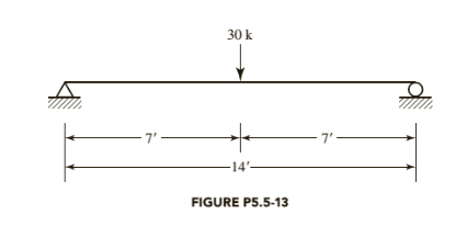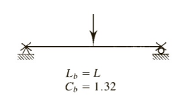
(a)
Whether a
Answer to Problem 5.5.14P
Inadequate
Explanation of Solution
Given:

Formula used:
Lpis unbraced length in an inelastic behavior
Lris unbraced length in an elastic behavior
Mn is nominal moment strength
Mpis plastic moment capacity
Calculation:
All channel shapes in the Manual are compact.(There are no footnotes to indicate otherwise)
For an
A is Cross-sectional area
Sxis Elastic section modulus about X -axis
Zxis Plastic section modulus about X -axis
Iyis Moment of inertia about Y -axis
ryis Radius of gyration about Y -axis
Syis Elastic section modulus about Y -axis
Cwis Warping constant
h0is Distance between centroid of flanges
J is Torsional moment of inertia
For channels,
For
From the below given figure in the textbook,

Conclusion:
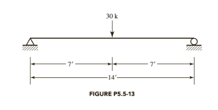
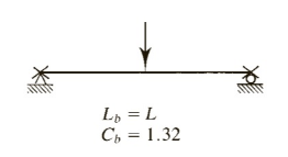
(b)
Whether a
Answer to Problem 5.5.14P
Inadequate
Explanation of Solution
Given:

Formula used:
Mn is nominal moment strength
Mpis plastic moment capacity
Calculation:
All channel shapes in the Manual are compact. (There are no footnotes to indicate otherwise)
For an
A is Cross-sectional area
Sxis Elastic section modulus about X -axis
Zxis Plastic section modulus about X -axis
Iyis Moment of inertia about Y -axis
ryis Radius of gyration about Y -axis
Syis Elastic section modulus about Y -axis
Cwis Warping constant
h0is Distance between centroid of flanges
J is Torsional moment of inertia
For channels,
For
From the below given figure in the textbook,

Conclusion:
Want to see more full solutions like this?
Chapter 5 Solutions
STEEL DESIGN W/ ACCESS
- Question 5. Three pipes A, B, and C are interconnected as in Fig. 2. The pipe characteristics are given below. Find the rate at which water will flow in each pipe. Find also the pressure at point P. (Neglect minor losses) Pipe D (in) L (ft) f A 6 2000 0.020 B 4 1600 0.032 C 8 3000 0.02 -El. 200 ft P -El. 120 ft B Fig. 2 -El. 50 ft.arrow_forwardcalculate all nodal displacementts and all the member forces of the trussarrow_forwardNOTE: Use areal methods only for V,M,N diagrams(Do NOT use the equations) (also draw the N diagram(s) for the entire structure)arrow_forward
- The figure below shows a foundation of 10 ft x 6.25 ft resting on a sand deposit. The net load per unit area at the level of the foundation, qo, is 2100 lb/ft². For the sand, μs = 0.3, E, = 3200 lb/in.², Dƒ = 2.5 ft, and H = 32 ft. Foundation BX L Rigid foundation settlement Flexible foundation settlement H μ, Poisson's ratio E, = Modulus of elasticity Soil Rock Elastic settlement of flexible and rigid foundations Table 1 Variation of F₁ with m' and n' m' n' 1.0 1.2 1.4 1.6 1.8 2.0 2.5 3.0 0.25 0.014 0.013 0.012 0.011 0.011 0.011 0.010 0.010 0.50 0.049 0.046 0.044 0.042 0.041 0.040 0.038 0.038 1.00 0.142 0.138 0.134 0.130 0.127 0.125 0.121 0.118 2.00 0.285 0.290 0.292 0.292 0.291 0.289 0.284 0.279 5.00 0.437 0.465 0.487 0.503 0.516 0.526 0.543 0.551 10.00 0.498 0.537 0.570 0.597 0.621 0.641 0.679 0.707 20.00 0.529 0.575 0.614 0.647 0.677 0.702 0.756 0.797 50.00 0.548 0.598 0.640 0.678 0.711 0.740 0.803 0.853 100.00 0.555 0.605 0.649 0.688 0.722 0.753 0.819 0.872 Table 2 Variation of F2…arrow_forward= == An 8 m high retaining wall supports a 5.5 m deep sand (Ya 18.5 kN/m³, q = 34°) overlying a saturated sandy clay (y_sat = 20.3 kN/m³, q = 28°, c = 17 kPa). The groundwater level is located at the interface of two layers. Sketch the lateral stress distribution up to a depth of 8 m for an active condition. Also, determine the line of action of the resultant. 5.5 m Sand |Y=18.5 kN/m³ |₁ =34° Sandy : clay 2.5 m |c=17 kPa Ysat 20.3 kN/m³ 2=28°arrow_forward3. What is the maximum allowable load that can be applied to the pile shown below? : Qall = ? G.W.T. 45' Soft Clay: Ysat 100 pcf Cu = 500 psf, ou = 0° Clay Shale: Qu(lab) 24,000 psi o' = 15° Driven Steel H-Pile: 1/2" thick steel web & flanges (soil plugged) -10". I Note: Pile & soil profile are not drawn to scale Please use the approach outlined in Das 12.16 and an Allowable Stress Design (ASD) approach for your analysis. Use a factor of safety = 3 for design, neglect any effect that shaft resistance has on pile capacity, and neglect the effect of the weight of the pile in your analysis.arrow_forward
- 2. Calculate the ultimate load carrying capacity of the pile tip driven into the soil profile shown below: G.W.T. Qapp 40' Soft Clay: Ysat 100 pcf Cu 500 psf, ₁ = 0° 4c+4 Poorly Graded Sand (SP): Ysat = 125 pcf Q₁ = ? c' = 0, ' = 35° Driven Steel Pipe Pile: Outside Diameter = 2' Inside Diameter = 1'11" Hollow (soil plugged) Note: Pile & soil profile are not drawn to scale For this problem, please calculate N₁* using both the bearing capacity theory approach and using standard design charts. Compare the values that result from these two approaches. Please use only the Nq* from bearing capacity theory for the remainder of your calculations.arrow_forwardDesign a fully restrained BFP moment connection to support the factored bending moment of 1,200 kN·m and factored shear force of 95 kN due to wind and gravity loads. Use 90mm spacing between the bolts, and 40mm edge spacing. The steel grade is A992 for the W920 × 201 beam and W840 × 359 column and A36 for the steel plate (30 mm thick). Use FEXX = 450 MPa electrodes and 20mm A490 bolts (threads included) for the flange plate (Fr= 457 MPa), 16mm A307 bolts for the shear tab (Fnv = 165 MPa). Steel Section Properties W920 × 201 W840 × 359 D₁ = 904 mm bf = 305 mm tf = 20.1 mm tw = 15.2 mm d = 869 mm bf = 404 mm tf = 35.6 mm tw = 21.1 mm Summary of answer: Flange Plate: bPL = tPL = No. of Bolts: Flange bolt = Thickness of fillet weld on shear tab:. Shear tab =arrow_forwardA6.1- A simply supported beam, as shown in Figure 3, is subjected to factored point load Pr= 1250 kN. The beam is designed to have 6-30M bars to resist the maximum bending moment, Mat the section 900 mm away from the centerline of the support. Determine the required development length for the reinforcement at the section with the maximum bending moment. If it is not possible to provide straight bar anchorage into the left support, design the hooked anchorage. Given: Concrete: Normal density with f'c = 25 MPa Reinforcement: Uncoated rebars with fy = 400 MPa Shear reinforcement is in excess of CSA 23.3 minimum requirement: 10M Clear cover to the stirrups: 30 mm Column: 200mm x 500mm m + 1 b=500 mm 200mm Σ Mf 6-30M Figure 3 10 m 200mm h=1000 mm + As = 6-30M Cross-sectionarrow_forward
- P What's the stress increase, DUZ (induced stress) at point p according to the chart shown? Show work and mark the chart to demonstrate how you came up with an answer 36ff Qis 24f+ P (at depth 12ft) Point R is below Q, which is on the edge of the footing. 24 ft from one corner (thus 12 from the other). Show how to divide the area into two and use the principle of Super position to calculate stress increase (DJ₂) aka induced stress at R. Draw a plan view of Area I and Arca 2. Find L1, B₁, and 2, dimensions and indicate them accordingly on both Area 1 and Area 2 24f1 - 24ft •R (depth 12ft)arrow_forward. For the cast-iron piping shown in Fig. 4, calculate the flow rate if H = 8 m. (e=0.26 mm, v=1.0×10m²/s) Include all losses.) 2 m Water H 20°C 20 m 40 m T 2 cm dia. 4 cm dia. Angle valve (wide open) (4.7)'arrow_forwardA5.2- A simply supported beam with the given cross-section, as shown in Figure 2, is subjected to factored uniform load of 50 kN/m. The designer would like to cut-off 2-30M bars where they are no longer required by the design. Determine the cut-off point for 2-30M bars according to CSA 23.3 requirements. Given: Concrete: Normal density with f'c = 30 MPa Reinforcement: Uncoated rebars with fy = 400 MPa Shear reinforcement is in excess of CSA 23.3 minimum requirement: 10M Clear cover to the stirrups: 40 mm Columns: 500 mm x 500 mm 9 m W= 50 kN/m Figure 2 h=600 mm b=500 mm Cross-section As = 5-30Marrow_forward
 Steel Design (Activate Learning with these NEW ti...Civil EngineeringISBN:9781337094740Author:Segui, William T.Publisher:Cengage Learning
 Materials Science And Engineering PropertiesCivil EngineeringISBN:9781111988609Author:Charles GilmorePublisher:Cengage Learning
 Engineering Fundamentals: An Introduction to Engi...Civil EngineeringISBN:9781305084766Author:Saeed MoaveniPublisher:Cengage Learning


