
(a)
The adequacy of the W 6 X12 beam for use as purlin using LRFD method.
Answer to Problem 5.5.16P
The beam is adequate to be used for purlin.
Explanation of Solution
Given:
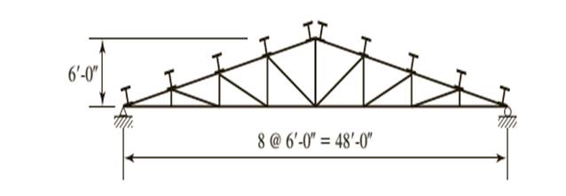
A truss with a roof system supporting a total gravity load of 40 psf of roof surface, half dead load and half snow. Spacing = 10 ft on centers.
Calculation:
Let’s calculate the nominal flexural strength about the X and Y axes.
Determine the strong axis bending strength. As neither the beam design charts nor the Z tables include shapes under W8 compute the flexural strength of W 6 X12. As there is no foot note to indicate otherwise the shape is compact.
We need to determine what controls the lateral torsional buckling.
Computing the values of
Substitute the values from the AISC Manual as
Substitute the values from the AISC Manual as
Now calculate the plastic moment for the section, we have
Where,
Substitute the values from the ASIC manual, we have
Let’s compare the values
Which implies that the strength is governed by inelastic Lateral- Torsional Buckling.
Compute the nominal strength of beam using the equation given as follows:
Substitute the values from the ASIC manual, we have
For the Y − axis, there is no flange buckling since the shape is compact.
Calculate the flexural strength about y- axis as:
Where,
Now, calculating the plastic moment of section about minor principal axis as:
Substitute the values, we have
Calculate the flexural strength about y axis, we have
Checking the upper limit using the following :
Substitute the values, we have
As the inequality is satisfied then the its OK.
Now using the LRFD method.
Following equation must be satisfied in order to know adhere to AISC specifications.
Where,
Now we need to find the values to substitute them
Where,
Where,
Where
As it is been given that half of load is dead load and half is snow load.
Therefore, as per the given conditions
Where,
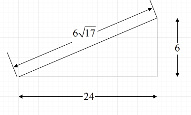
Following is the diagram from which we can find the value of angles.

Substitute the value for H = 6 ft and
Substitute the values
Substitute,
Find the flexural load about x-axis,
Similarly, for
Where,
Substitute,
Find the flexural load about x-axis,
Now, find the values of
As we have found every value, now we can substitute the values and check the adequacy
The equation is hence satisfied.
Conclusion:
Therefore, the beam is adequate.
(b)
The adequacy of W 6 X12 beam for use as purlin using ASD method.
Answer to Problem 5.5.16P
The beam is adequate to be used for purlin.
Explanation of Solution
Given:
A truss with a roof system supporting a total gravity load of 40 psf of roof surface, half dead load and half snow. Spacing = 10 ft on centers.

Calculation:
Now from Allowable stress design
Where
Now find the value of
Where,
Where,
Where
As it is been given that half of load is dead load and half is snow load.
Therefore, as per the given conditions
Calculate the load on the purlin as follows:
Following is the diagram from which we can find the value of angles.
Where,
Substitute the value for H = 6 ft and
Load on the purlin is as follows:
Substitute the values, we have
Now,
Where, L is the length of the beam and
Where,
Substitute the values, we have
Now find the value of
As we have found every value, now we can substitute the values and check the adequacy
Hence, the equation is satisfied.
Conclusion:
Therefore, the beam is adequate.
Want to see more full solutions like this?
Chapter 5 Solutions
STEEL DESIGN W/ ACCESS

- *8-60. The 2-in.-diameter rod is subjected to the forces shown. Determine the state of stress at point B, and show the results on a differential element located at this point. Probs. 8-59/60 B 8 in. 600 lb 12 in. 500 lb 800 lbarrow_forwardfind SFD and BMD by using slope deflection methodarrow_forwardThe following relates to Problems 4 and 5. Christchurch, New Zealand experienced a major earthquake on February 22, 2011. It destroyed 100,000 homes. Data were collected on a sample of 300 damaged homes. These data are saved in the file called CIEG315 Homework 4 data.xlsx, which is available on Canvas under Files. A subset of the data is shown in the accompanying table. Two of the variables are qualitative in nature: Wall construction and roof construction. Two of the variables are quantitative: (1) Peak ground acceleration (PGA), a measure of the intensity of ground shaking that the home experienced in the earthquake (in units of acceleration of gravity, g); (2) Damage, which indicates the amount of damage experienced in the earthquake in New Zealand dollars; and (3) Building value, the pre-earthquake value of the home in New Zealand dollars. PGA (g) Damage (NZ$) Building Value (NZ$) Wall Construction Roof Construction Property ID 1 0.645 2 0.101 141,416 2,826 253,000 B 305,000 B T 3…arrow_forward
- find SFD and BMDarrow_forwardThe data needed to answer this question is given by this link: https://docs.google.com/spreadsheets/d/1vzb03U7Uvzm7X-by3OchQNwYeREzbP6Z-xzZMP2tzNw/edit?usp=sharing if it is easier to make a copy of the data because it is on view only then feel free to do so.arrow_forwardThe data needed to answer this question is given in the following link (file is on view only so if you would like to make a copy to make it easier for yourself feel free to do so) https://docs.google.com/spreadsheets/d/1aV5rsxdNjHnkeTkm5VqHzBXZgW-Ptbs3vqwk0SYiQPo/edit?usp=sharingarrow_forward
- The benchmark is 00.00. The backsights are 6.00, 9.32 and 13.75 and 14.00 The foresights are 6.00, 9.00 and 3.22. What is the height of the instrument? H.I. - 100.00 - 124.85 - 43.07- 24.85arrow_forwardThe benchmark is 100.00. The backsights are 4.00, 6.32 and 12.75. The foresights are 6.00, 9.00 and 3.22. What is the elevation of the point? - 95.14 - 123.08 - 104.85 - 81.78arrow_forwardDetermine the stiffness matirx of the entire truss in Global co-ordinate system, clearly indicate the degrees of freedom numbers in the stiffness matrix.arrow_forward
 Steel Design (Activate Learning with these NEW ti...Civil EngineeringISBN:9781337094740Author:Segui, William T.Publisher:Cengage Learning