
EBK ELECTRICAL ENGINEERING
7th Edition
ISBN: 8220106714201
Author: HAMBLEY
Publisher: YUZU
expand_more
expand_more
format_list_bulleted
Concept explainers
Videos
Textbook Question
Chapter 5, Problem 5.12P
Calculate the rms value of the half-wave rectified sine wave shown in Figure P5.12.
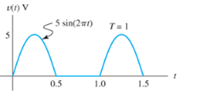
Figure P5.12
Expert Solution & Answer
Want to see the full answer?
Check out a sample textbook solution
Students have asked these similar questions
Don't use ai to answer I will report you answer
Only expert tutors should solve the question, don't use any Ai or it's screen shot.
Use your knowledge skills
DO NOT USE AI NEED PEN PAPER SOLUTIONIn the following circuit, the current through the 1.0 ohm resistor is 455 mA. Using Kirchhoff's Laws, find the currents through the 2.0 ohm and 3.0 ohm resistors. 1.0Ω
Chapter 5 Solutions
EBK ELECTRICAL ENGINEERING
Ch. 5 - Consider the plot of the sinusoidal voltage...Ch. 5 - Repeat Problem P5.3 for v(t) = 50 sin (500t+120) .Ch. 5 - A sinusoidal voltage v(t) has an rms value of 20...Ch. 5 - A current i(t)=10cos(2000t) flows through a 100...Ch. 5 - We have a voltage v(t)=1000sin(500t) across a 500...Ch. 5 - Calculate the rms value of the half-wave rectified...Ch. 5 - We have v1(t)=10cos(t+30) . The current i1(t)has...Ch. 5 - Solve for the mesh currents shown in Figure P5.55.Ch. 5 - Two loads. A and B, are connected in parallel...
Knowledge Booster


Learn more about
Need a deep-dive on the concept behind this application? Look no further. Learn more about this topic, electrical-engineering and related others by exploring similar questions and additional content below.Similar questions
- HANDWRITTEN SOLUTION NOT USING AI In the following circuit, the current through the 1.0 ohm resistor is 455 mA. Using Kirchhoff's Laws, find the currents through the 2.0 ohm and 3.0 ohm resistors. 1.0Ωarrow_forwardthe answere is not 4.16arrow_forwardIncorrect Question 13 It has 16 address lines 8-bit bus, 16-bit address bus 16 bit bus, 8-bit address bus 8-bit bus. 8-bit address bus 16-bit bus, 16-bit address busarrow_forward
- DO NOT USE AI NEED HANDWRITTEN SOLUTIONarrow_forwardEach branch of a three-phase star-connected load consists of a coil of resistance 4.2 Ω and reactance 5.6 Ω. The load is supplied at a line voltage of 400 V, 50 Hz. The total active power supplied to the load is measured by the two-wattmeter method. Draw a circuit diagram of the wattmeter connections and calculate their separate readings. Derive any formula used in your calculations. ANS: 13.1 kW, 1.71 kWarrow_forwardThree non-reactive loads are connected in delta across a three-phase, three-wire, 400 V supply in the following way: (i) 10 kW across R and Y lines; (ii) 6 kW across Y and B lines; (iii) 4 kW across B and R lines. Draw a phasor diagram showing the three line voltages and the load currents and determine: (a) the current in the B line and its phase relationship to the line voltage VBR; (b) the reading of a wattmeter whose current coils are connected in the B line and whose voltage circuit is connected across the B and R lines. The phase rotation is R–Y–B. Where would a second wattmeter be connected for the two-wattmeter method and what would be its reading? ANS: 21.8 A, 36°35′ lagging; 7 kW; 13 kWarrow_forward
- NEED HANDWRITTEN SOLUTION DO NOT USE AI OR CHATGPTarrow_forwardA factory has the following load with power factor of 0.85 lagging in each phase. Between the red and yellow phases 40 A, between the yellow and blue phases 50 A, and between the blue and red phases 60 A. If the supply is 415 V, three-phase, calculate the line currents. Draw a phasor diagram for phase and line quantities. Ensure to draw all necessary diagrams ANS: IR = 87.178<-68.380 A; IY = 78.102<-178.120 A; IB = 95.394<61.210 A.arrow_forwardAnswer question D only using by hand first darw cylinder then calculate show me starrow_forward
arrow_back_ios
SEE MORE QUESTIONS
arrow_forward_ios
Recommended textbooks for you
 Power System Analysis and Design (MindTap Course ...Electrical EngineeringISBN:9781305632134Author:J. Duncan Glover, Thomas Overbye, Mulukutla S. SarmaPublisher:Cengage Learning
Power System Analysis and Design (MindTap Course ...
Electrical Engineering
ISBN:9781305632134
Author:J. Duncan Glover, Thomas Overbye, Mulukutla S. Sarma
Publisher:Cengage Learning
What Is a Plane Wave? — Lesson 2; Author: EMViso;https://www.youtube.com/watch?v=ES2WFevGM0g;License: Standard Youtube License