
Concept explainers
Determine the Norton equivalent of the circuit depicted in Fig. 5.74 as seen looking into the two open terminals. (b) Compute power dissipated in a 5 Ω resistor connected in parallel with the existing 5 Ω resistor. (c) Compute the current flowing through a short circuit connecting the two terminals.
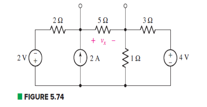
(a)
Find the Norton equivalent of the circuit as seen looking into the two open terminals.
Answer to Problem 33E
The Norton current is
Explanation of Solution
Formula used:
The expression for voltage is as follows.
Here,
The expression for series combination of resistance is as follows.
Here,
The expression for parallel combination of resistance is as follows.
Here,
Calculation:
The circuit diagram is redrawn as shown in Figure 1.
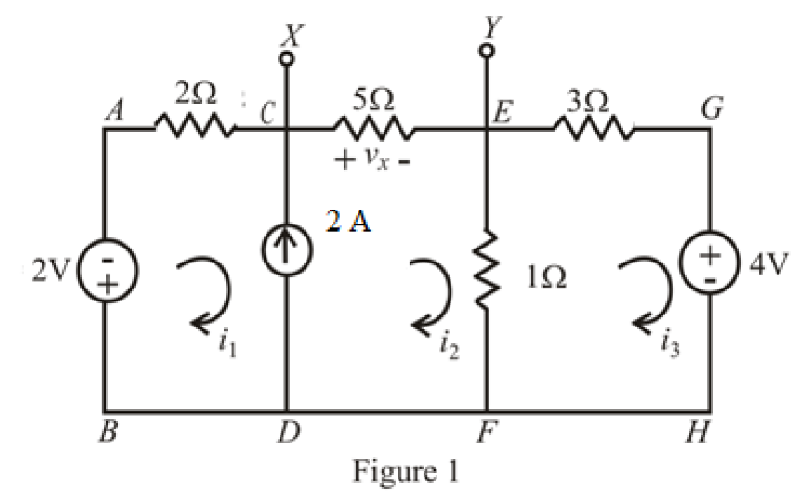
Refer to redrawn Figure 1,
The expression for KVL in super mesh
Here,
Substitute
The expression for KVL in mesh
Here,
Substitute
The expression for current
Here,
Substitute
Rearrange equations(5),(7) and (9).
The equations so formed can be written in matrix form as,
Therefore, by Cramer’s rule,
The determinant of coefficient matrix is as follows.
The 1st determinant is as follows.
The 2nd determinant is as follows,
The 3rd determinant is as follows.
Simplify for
Simplify for
Simplify for
Substitute
So, the Thevenin voltage is
The circuit diagram is redrawn as shown in Figure 2.
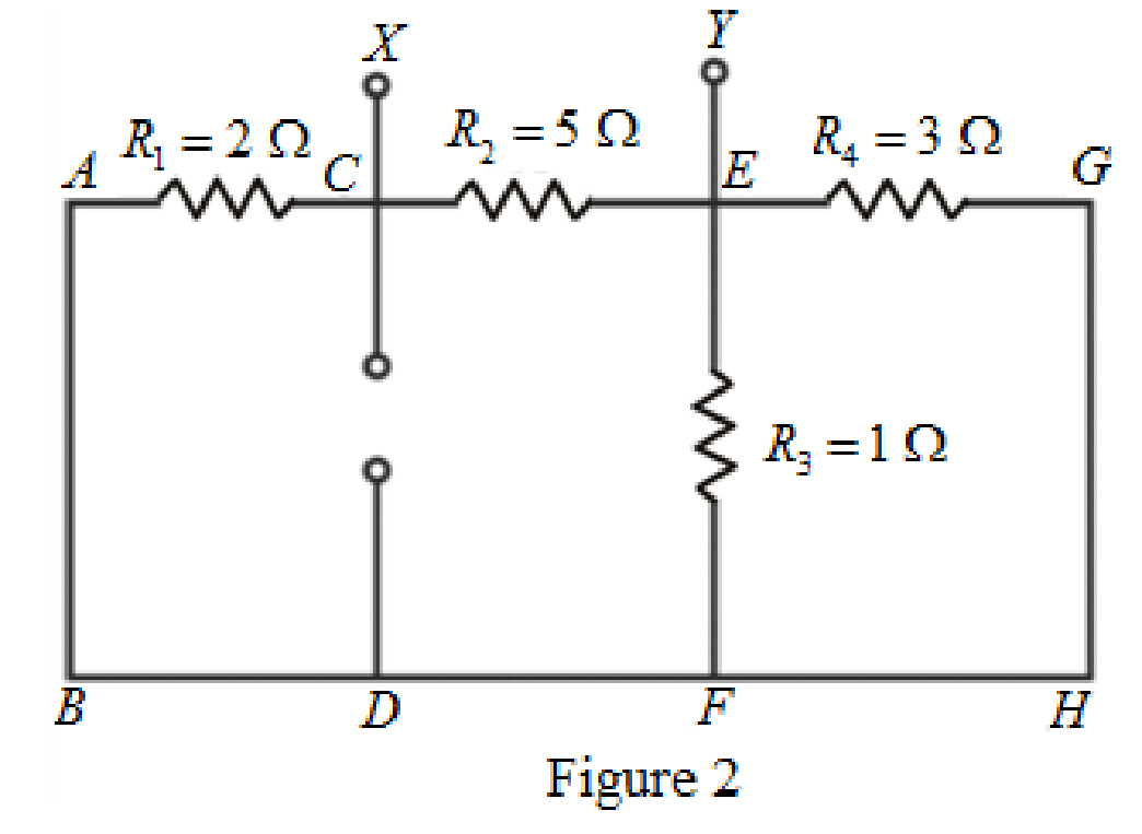
As
Rearrange for
The circuit diagram is redrawn as shown in Figure 3.
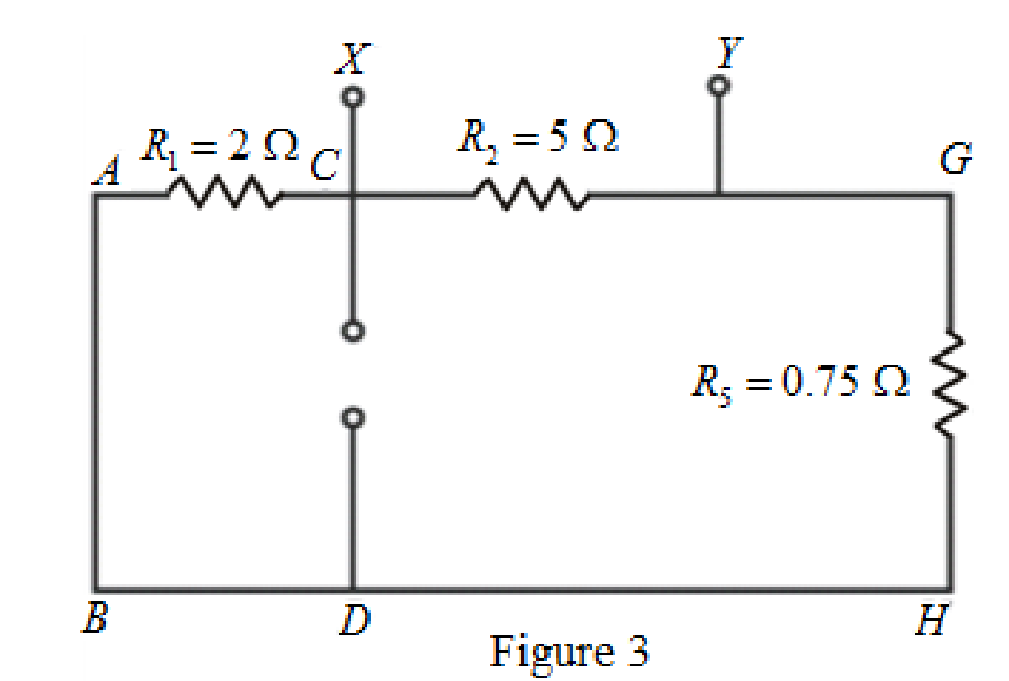
As
The circuit diagram is redrawn as shown in Figure 4.
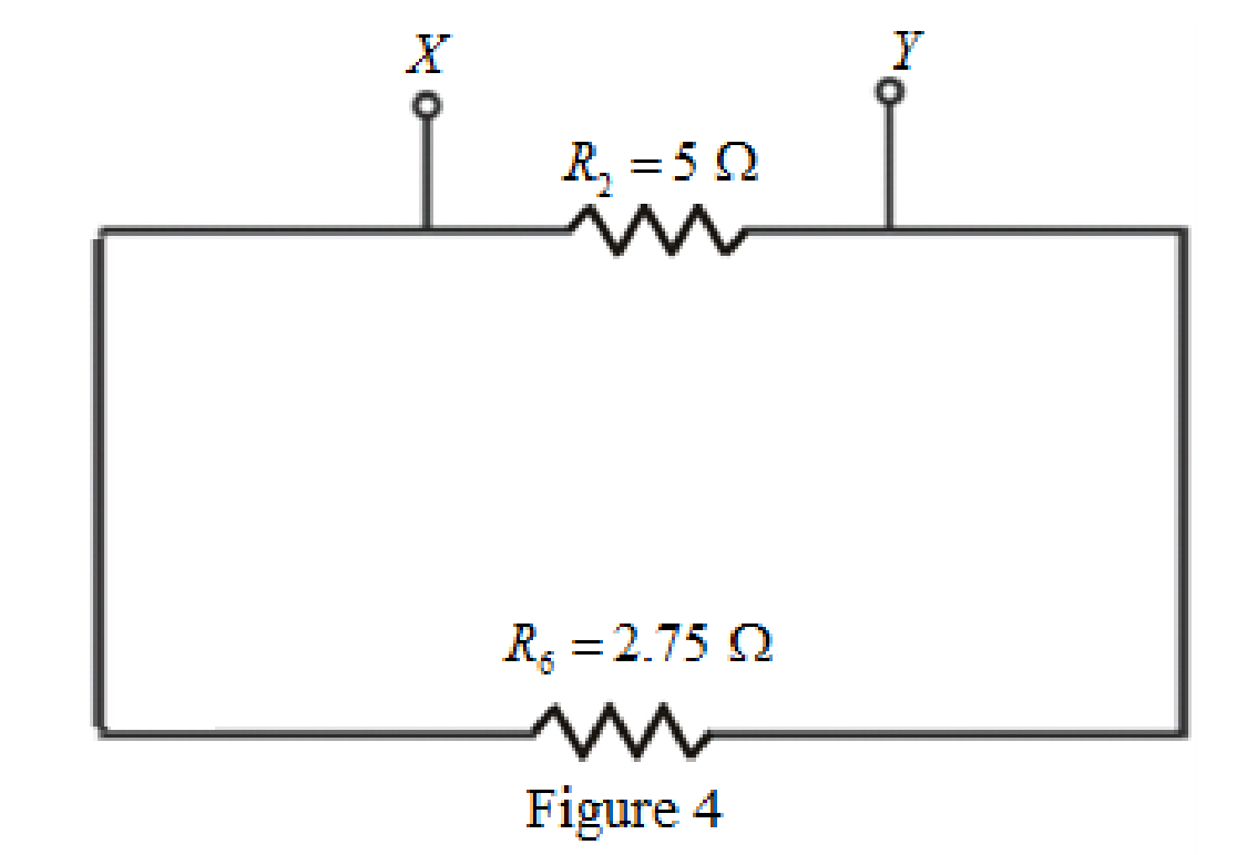
Refer to redrawn Figure 4,
As
Rearrange for
So, the Thevenin equivalent resistance across the branch
Thevenin equivalent resistance is same as the Norton equivalent resistance,
Hence,
The circuit diagram is redrawn as shown in Figure 5,
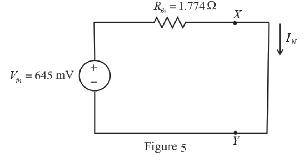
Refer to redrawn Figure 5,
Norton current is the current in the load resistor when load resistance is replaced by a short circuit.
The expression for the Norton current flowing in the circuit is as follows,
Here,
Substitute
Conclusion:
Thus the Norton current is
(b)
Find the power dissipated in a
Answer to Problem 33E
The power dissipated in a
Explanation of Solution
Given Data:
The load resistance is
Formula used:
The expression for the power dissipated in a resistor is as follows,
Here,
Calculation:
The circuit is drawn as shown in Figure 6,
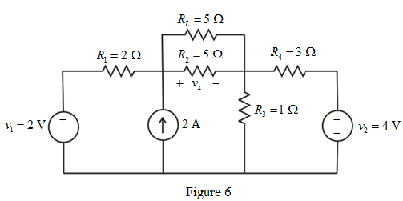
Refer to redrawn Figure 6,
The simplified Norton equivalent of the circuit is drawn as shown in Figure 7,
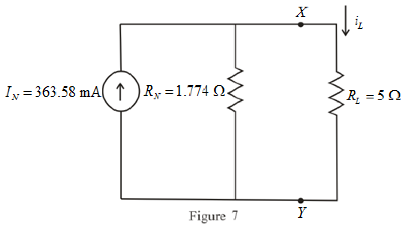
Refer to redrawn Figure 7,
The expression for the current flowing through the load is as follows,
Substitute
Substitute
Conclusion:
Thus, the power dissipated in a
(c)
Find the current flowing through a short circuit connecting the two terminals.
Answer to Problem 33E
The current flowing through a short circuit connecting the two terminals is
Explanation of Solution
Calculation:
The current flowing through a short circuit connecting the two terminals is Norton current which is
So, the current flowing through a short circuit connecting the two terminals is
Conclusion:
Thus, the current flowing through a short circuit connecting the two terminals is
Want to see more full solutions like this?
Chapter 5 Solutions
Engineering Circuit Analysis
- Please show the solution and answers in each. Thank you. A 120 MVA, 19.5 kV generator has Xₛ = 1.5 pu and is connected to a transmission line by a transformer rated 150 MVA , 230 wye/18 delta kV Watts, and X = 0.1 pu. If the base to be used in the calculation is 100 MVA, 230 kV for the transmission line. a. Find the per-unit values to be used for the transformer and generator reactances. b. If the transformer delivers 80% of its rated capacity to the line at 220 kV, express the current in per unit. c. Find also the current in the genrator in amperes.arrow_forwardI need an expert mathematical solution. The radiation intensity of an aperture antenna, mounted on an infinite ground plane with perpendicular to the aperture. is rotationally symmetric (not a function of 4), and it is given by U sin (77 sin 0) π sin Find the approximate directivity (dimensionless and in dB) using numerical integration. Use the DIRECTIVITY computer program at the end of this chapter.arrow_forwardDon't use ai to answer I will report you answer.arrow_forward
- The E-field pattern of an antenna. independent of , varies as follows: E 0 0° ≤ 0≤ 45° 45°<≤ 90° 90° <8180° (a) What is the directivity of this antenna? Umax 7 why did we use this law Umax = 12 but we divided by 2? In the sent Solution = R 27arrow_forwardThe normalized far-zone field pattern of an antenna is given by (sin cos²) E = 0 00 and 0 ≤ ≤ π/2. 3/22 π elsewhere Find the directivity using (a) the exact expression In the sent soalation Use Prad=2+1 7/2 Pre= 2 + 1 Sco³odo + 5 siño de Where did the 2 Com from?arrow_forwardPen and paper solution please with explaination not using chatgptarrow_forward
- howarrow_forwardA four pole generator having wave wound armature winding has 51 slots ,each slot containing 20 conductors,what will be the voltage generated in the machine when driven at 1500rpm assuming the flux per pole is 7mWb Don't use Artificial intelligencearrow_forwardNeed Handwritten solution Do not use chatgpt Or AIarrow_forward
 Introductory Circuit Analysis (13th Edition)Electrical EngineeringISBN:9780133923605Author:Robert L. BoylestadPublisher:PEARSON
 Delmar's Standard Textbook Of ElectricityElectrical EngineeringISBN:9781337900348Author:Stephen L. HermanPublisher:Cengage Learning
 Programmable Logic ControllersElectrical EngineeringISBN:9780073373843Author:Frank D. PetruzellaPublisher:McGraw-Hill Education
 Fundamentals of Electric CircuitsElectrical EngineeringISBN:9780078028229Author:Charles K Alexander, Matthew SadikuPublisher:McGraw-Hill Education
 Electric Circuits. (11th Edition)Electrical EngineeringISBN:9780134746968Author:James W. Nilsson, Susan RiedelPublisher:PEARSON
 Engineering ElectromagneticsElectrical EngineeringISBN:9780078028151Author:Hayt, William H. (william Hart), Jr, BUCK, John A.Publisher:Mcgraw-hill Education,


