Concept explainers
Find the Thevenin equivalent of the circuit.
Answer to Problem 45E
The Thevenin voltage is
Explanation of Solution
Calculation:
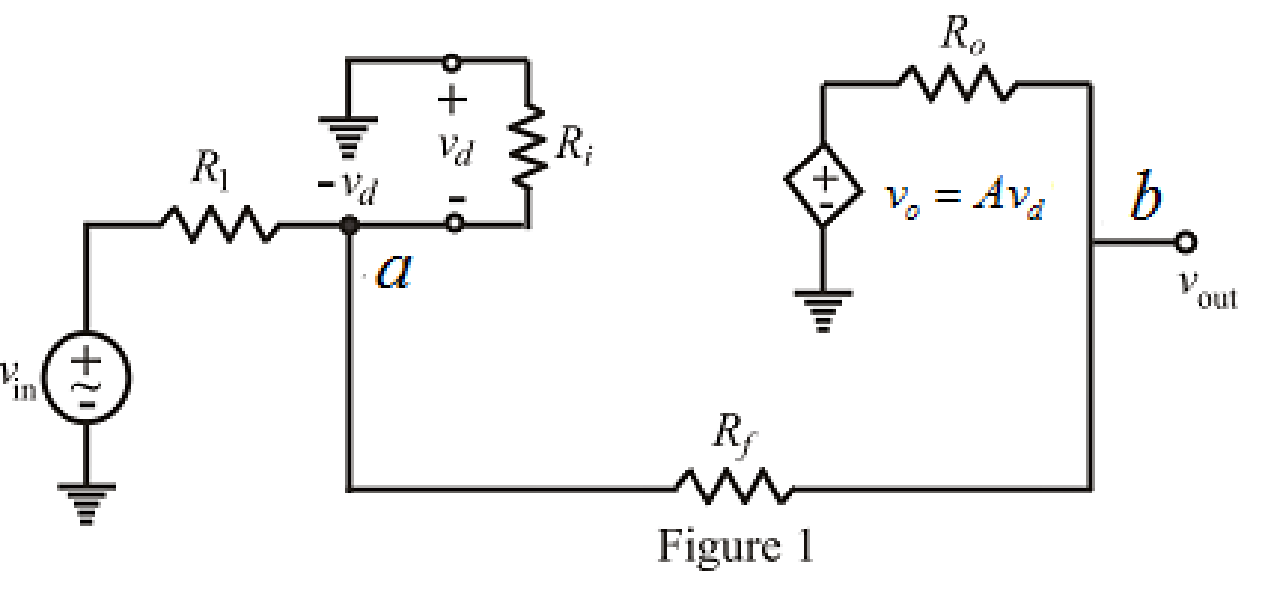
The redrawn circuit diagram is given in Figure 1,

Refer to Figure 1,
Apply Kirchhoff’s current law at node
Here,
Rearrange equation (1),
Apply Kirchhoff’s current law at node
Here,
Substitute
Rearrange for
Substitute
Rearrange the equation for
Modify the equation as,
Write the equation to find voltage
So, the Thevenin voltage is
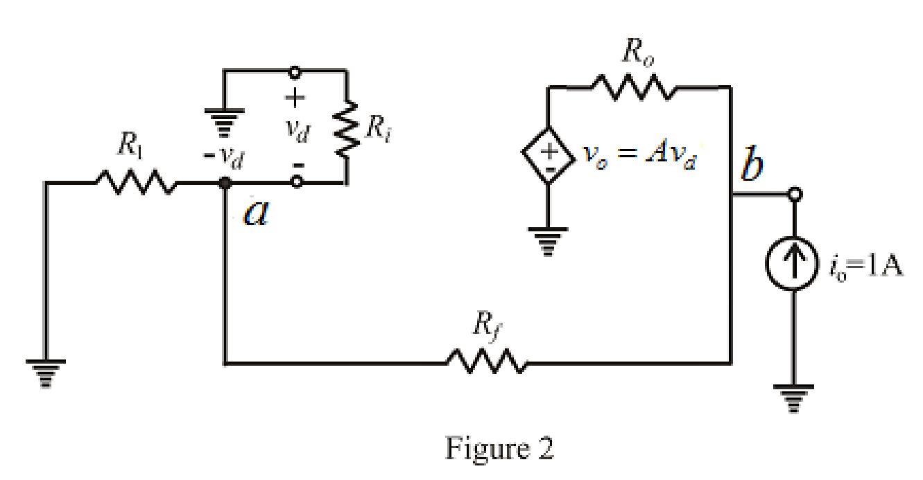
To find equivalent resistance of a circuit the independent voltage source replaced by short circuit and load resistor is disconnected and
The redrawn circuit diagram is given in Figure 2,

Refer to the redrawn Figure 2,
Apply Kirchhoff’s current law at node
Rearrange for
Apply Kirchhoff’s current law at node
Substitute
Substitute
Rearrange for
The expression for the Thevenin equivalent resistance is as follows,
Substitute
So, the Thevenin equivalent resistance is
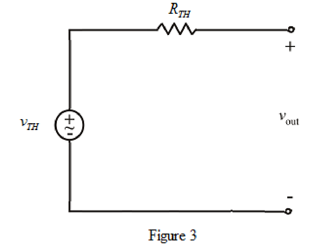
The Thevenin equivalent circuit is drawn as shown in Figure 3,

Conclusion:
Thus, the Thevenin voltage is
Want to see more full solutions like this?
Chapter 5 Solutions
Engineering Circuit Analysis
- I just want a human answerarrow_forwardDesign a synchronous Up/Down counter to produce the following sequence (4 9 2,0,7,6,3,1,5) using T flip-flop. The counter should count up when Up/Down =1, and down when Up/Down = 0.arrow_forwardQ2: Using minimum number of D flip-flops, design a synchrounus counter. The counter counts in the sequence 0,15,2,7,0,15,....... When its enable input x is equal to 1; otherwise the counter is idle.arrow_forward
- Design a synchronous Up/Down counter to produce the following sequence (4 9 2,0,7,6,3,1,5) using T flip-flop. The counter should count up when Up/Down =1, and down when Up/Down = 0.arrow_forwardCan you elaborate on how to determine the direction along with solving the requirements? A uniform plane wave propagation in media has: र E = 2 e sin (let-pz) ay Erol, Mr = 20, 6-35/m Find α, B, πarrow_forwardCan you elaborate on how to determine the direction along with solving the requirements? in a lossless medium for which Robons Myst, and has; πl=- = - al cos (wt-z) ax +0.5 Silwt-z) ay Ahm Calculate Er, W, Earrow_forward
- V/m the electric field in free space is given by E. 50 Cos [2π lot - B2] ay a) find the direction of the wave propagation b) Calculate W, B, A, Sarrow_forward4- magnetic medium Ex:- A plane wave in non-. (Mr=1) has: E. 50 Sin (10³t + 2Z) ay v/m a) direction of propagation and H- b) A, f, Er, dp Solution f Z хн Wave His in ax Wave is in az B=2, w=10 8 YE How?arrow_forwardCan you elaborate on how to determine the direction along with solving the requirements? A plane wave in non- (Mr=t) has: magnetic medium E. 50 Sin (10³t + 2Z) ay v/m a) direction of propagann and H. b) A, f, Er, dp H&arrow_forward
- B:Find the roots of the following equation using NR method at the end of second iteration.start with V-4, V2-8 V₁*V2-50.... (1) Vi+V2 =15... (2)arrow_forwardB:Find the roots of the following equation using NR method at the end of second iteration.start with V-4, V2S V₁*V2=50... V₁+V₂ =15 (1)arrow_forwarda) Determine the setting of the overload protection of the circuit breaker intended to protect a 50hp, 380V, IV-pole motor, powered by a unipolar copper-PVC conductor circuit, with a cross-section of 25mm², installed in a buried conduit: The short-circuit current at the motor terminal is 5KA. It is assumed that the overload current of the conductor throughout its useful life is controlled and will not exceed 100 hours for 12 consecutive months or 500 hours throughout the useful life of the conductor. Data: fp = 0.86; efficiency = 0.92 a) Determine the minimum operating time of the circuit breaker in the event of a short-circuit at the motor terminals.arrow_forward
 Introductory Circuit Analysis (13th Edition)Electrical EngineeringISBN:9780133923605Author:Robert L. BoylestadPublisher:PEARSON
 Delmar's Standard Textbook Of ElectricityElectrical EngineeringISBN:9781337900348Author:Stephen L. HermanPublisher:Cengage Learning
 Programmable Logic ControllersElectrical EngineeringISBN:9780073373843Author:Frank D. PetruzellaPublisher:McGraw-Hill Education
 Fundamentals of Electric CircuitsElectrical EngineeringISBN:9780078028229Author:Charles K Alexander, Matthew SadikuPublisher:McGraw-Hill Education
 Electric Circuits. (11th Edition)Electrical EngineeringISBN:9780134746968Author:James W. Nilsson, Susan RiedelPublisher:PEARSON
 Engineering ElectromagneticsElectrical EngineeringISBN:9780078028151Author:Hayt, William H. (william Hart), Jr, BUCK, John A.Publisher:Mcgraw-hill Education,


