
Statics and Mechanics of Materials (5th Edition)
5th Edition
ISBN: 9780134382593
Author: Russell C. Hibbeler
Publisher: PEARSON
expand_more
expand_more
format_list_bulleted
Concept explainers
Videos
Textbook Question
Chapter 4.8, Problem 4PP
Determine the friction force at the surface of contact.
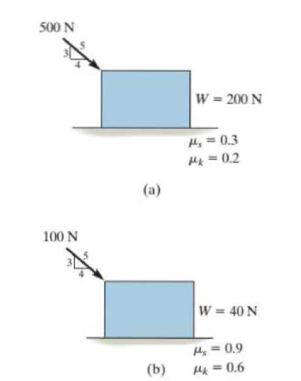
Prob. P4-4
Expert Solution & Answer

Trending nowThis is a popular solution!

Students have asked these similar questions
32 mm
32 mm
b'
c'
C
32 mm
32 mm
b
PROBLEM 6.41
a
The extruded beam shown has a uniform wall thickness of 3 mm. Knowing that
the vertical shear in the beam is 9 kN, determine the shearing stress at each of the
five points indicated.
In a structural reliability problem, the resistance (capacity) R and load effect (demand) S random variables
associated with a failure mode of the structure of interest are normally distributed and statistically
independent with the following probability distribution parameters (or statistics) in consistent units:
MR = 12, σR = 3
μs = 5, σs = 2
(a) Determine the exact probability of failure pF ·
The resistance R and load effect S for a given failure mode are statistically independent random variables
with marginal PDF's
1
fR (r) =
0≤r≤100
100'
fs(s)=0.05e-0.05s
(a) Determine the probability of failure by computing the probability content of the failure domain defined
as {r
Chapter 4 Solutions
Statics and Mechanics of Materials (5th Edition)
Ch. 4.4 - Draw the free-body diagram of each object. Prob....Ch. 4.4 - Determine the horizontal and vertical components...Ch. 4.4 - Determine the horizontal and vertical components...Ch. 4.4 - The truss is supported by a pin at A and a roller...Ch. 4.4 - Determine the components of reaction at the fixed...Ch. 4.4 - The 25-kg bar has a center of mass at G. If it is...Ch. 4.4 - Determine the reactions at the smooth contact...Ch. 4.4 - Determine the components of the support reactions...Ch. 4.4 - Determine the reactions at the supports. Prob. 4-2Ch. 4.4 - Determine the horizontal and vertical components...
Ch. 4.4 - Determine the reactions at the supports. Prob. 4-4Ch. 4.4 - Determine the reactions at the supports. Prob. 4-5Ch. 4.4 - Determine the reactions at the supports. Prob. 4-6Ch. 4.4 - Determine the magnitude of force at the pin A and...Ch. 4.4 - The dimensions of a jib crane are given in the...Ch. 4.4 - The dimensions of a jib crane are given in the...Ch. 4.4 - The smooth pipe rests against the opening at the...Ch. 4.4 - The beam is horizontal and the springs are...Ch. 4.4 - The 10-kg uniform rod is pinned at end A. If it is...Ch. 4.4 - The man uses the hand truck to move material up...Ch. 4.4 - Three uniform books, each having a weight W and...Ch. 4.4 - Determine the reactions at the pin A and the...Ch. 4.4 - If rope BC will fail when the tension becomes 50...Ch. 4.4 - Prob. 17PCh. 4.4 - Prob. 18PCh. 4.4 - The cantilever footing is used to support a wall...Ch. 4.4 - Prob. 20PCh. 4.4 - A boy stands out at the end of the diving board,...Ch. 4.4 - Prob. 22PCh. 4.4 - Prob. 23PCh. 4.4 - Prob. 24PCh. 4.4 - Prob. 25PCh. 4.4 - The man attempts to pull the four wheeler up the...Ch. 4.6 - Draw the free-body diagram of each object.Ch. 4.6 - In each case, write the moment equations about the...Ch. 4.6 - Prob. 7FPCh. 4.6 - Prob. 8FPCh. 4.6 - The rod is supported by smooth journal bearings at...Ch. 4.6 - Determine the support reactions at the smooth...Ch. 4.6 - Determine the force developed in the short link...Ch. 4.6 - Determine the components of reaction that the...Ch. 4.6 - The uniform load has a mass of 600 kg and is...Ch. 4.6 - Due to an unequal distribution of fuel in the wing...Ch. 4.6 - Determine the components of reaction at the fixed...Ch. 4.6 - The 50-lb mulching machine has a center of gravity...Ch. 4.6 - Prob. 30PCh. 4.6 - The uniform concrete slab has a mass of 2400 kg....Ch. 4.6 - Prob. 32PCh. 4.6 - Determine the tension in each cable and the...Ch. 4.6 - The bent rod is supported at A, B, and C by smooth...Ch. 4.6 - Prob. 35PCh. 4.6 - The bar AB is supported by two smooth collars. At...Ch. 4.6 - The rod has a weight of 6 lb/ft. If it is...Ch. 4.6 - The sign has a mass of 100 kg with center of mass...Ch. 4.6 - Both pulleys cite fixed to the shaft and as the...Ch. 4.6 - Both pulleys are fixed to the shaft and as the...Ch. 4.6 - Prob. 41PCh. 4.8 - Determine the friction force at the surface of...Ch. 4.8 - Determine the couple moment M needed to cause...Ch. 4.8 - Prob. 6PPCh. 4.8 - Prob. 7PPCh. 4.8 - Prob. 13FPCh. 4.8 - Determine the minimum force P to prevent the 30-kg...Ch. 4.8 - Determine the maximum force P that can be applied...Ch. 4.8 - Prob. 16FPCh. 4.8 - Prob. 17FPCh. 4.8 - Prob. 18FPCh. 4.8 - Prob. 19FPCh. 4.8 - If the coefficient of static friction at all...Ch. 4.8 - Prob. 21FPCh. 4.8 - Prob. 42PCh. 4.8 - The tractor exerts a towing force T = 400 lb....Ch. 4.8 - The mine car and its contents have a total mass of...Ch. 4.8 - The winch on the truck is used to hoist the...Ch. 4.8 - Prob. 46PCh. 4.8 - The automobile has a mass of 2 Mg and center of...Ch. 4.8 - Prob. 48PCh. 4.8 - Prob. 49PCh. 4.8 - Prob. 50PCh. 4.8 - Determine the angle at which the applied force P...Ch. 4.8 - Prob. 52PCh. 4.8 - The 180-lb man climbs up the ladder and stops at...Ch. 4.8 - The 180-lb man climbs up the ladder and stops at...Ch. 4.8 - The spool of wire having a weight of 300 lb rests...Ch. 4.8 - The spool of wire having a weight of 300 lb rests...Ch. 4.8 - The ring has a mass of 0.5 kg and is resting on...Ch. 4.8 - Determine the smallest force P that must be...Ch. 4.8 - The man having a weight of 200 lb pushes...Ch. 4.8 - The uniform hoop of weight W is subjected to the...Ch. 4.8 - Prob. 61PCh. 4.8 - Prob. 62PCh. 4.8 - Prob. 63PCh. 4.8 - The coefficient of static Friction between the...Ch. 4 - If the roller at B can sustain a maximum load of 3...Ch. 4 - Determine the reactions at the supports A and B...Ch. 4 - Determine the normal reaction at the roller A and...Ch. 4 - Determine the horizontal and vertical components...Ch. 4 - Determine the x, y, z components of reaction at...Ch. 4 - Prob. 6RPCh. 4 - Prob. 7RPCh. 4 - The uniform 60-kg crate C rests uniformly on a...
Knowledge Booster


Learn more about
Need a deep-dive on the concept behind this application? Look no further. Learn more about this topic, mechanical-engineering and related others by exploring similar questions and additional content below.Similar questions
- Please solve this problem as soon as possible My ID# 016948724arrow_forwardThe gears shown in the figure have a diametral pitch of 2 teeth per inch and a 20° pressure angle. The pinion rotates at 1800 rev/min clockwise and transmits 200 hp through the idler pair to gear 5 on shaft c. What forces do gears 3 and 4 transmit to the idler shaft? TS I y 18T 32T This a 12 x 18T C 48T 5arrow_forwardQuestion 1. Draw 3 teeth for the following pinion and gear respectively. The teeth should be drawn near the pressure line so that the teeth from the pinion should mesh those of the gear. Drawing scale (1:1). Either a precise hand drawing or CAD drawing is acceptable. Draw all the trajectories of the involute lines and the circles. Specification: 18tooth pinion and 30tooth gear. Diameter pitch=P=6 teeth /inch. Pressure angle:20°, 1/P for addendum (a) and 1.25/P for dedendum (b). For fillet, c=b-a.arrow_forward
- 5. The figure shows a gear train. There is no friction at the bearings except for the gear tooth forces. The material of the milled gears is steel having a Brinell hardness of 170. The input shaft speed (n2) is 800 rpm. The face width and the contact angle for all gears are 1 in and 20° respectively. In this gear set, the endurance limit (Se) is 15 kpsi and nd (design factor) is 2. (a) Find the revolution speed of gear 5. (b) Determine whether each gear satisfies the design factor of 2.0 for bending fatigue. (c) Determine whether each gear satisfies the design factor of 2.0 for surface fatigue (contact stress). (d) According to the computation results of the questions (b) and (c), explain the possible failure mechanisms for each gear. N4=28 800rpm N₁=43 N5=34 N₂=14 P(diameteral pitch)=8 for all gears Coupled to 2.5hp motorarrow_forward1. The rotating steel shaft is simply supported by bearings at points of B and C, and is driven by a spur gear at D, which has a 6-in pitch diameter. The force F from the drive gear acts at a pressure angle of 20°. The shaft transmits a torque to point A of TA =3000 lbĘ in. The shaft is machined from steel with Sy=60kpsi and Sut=80 kpsi. (1) Draw a shear force diagram and a bending moment diagram by F. According to your analysis, where is the point of interest to evaluate the safety factor among A, B, C, and D? Describe the reason. (Hint: To find F, the torque Tд is generated by the tangential force of F (i.e. Ftangential-Fcos20°) When n=2.5, K=1.8, and K₁ =1.3, determine the diameter of the shaft based on (2) static analysis using DE theory (note that fatigue stress concentration factors need to be used for this question because the loading condition is fatigue) and (3) a fatigue analysis using modified Goodman. Note) A standard diameter is not required for the questions. 10 in Darrow_forward3 N2=28 P(diametral pitch)=8 for all gears Coupled to 25 hp motor N3=34 Full depth spur gears with pressure angle=20° N₂=2000 rpm (1) Compute the circular pitch, the center-to-center distance, and base circle radii. (2) Draw the free body diagram of gear 3 and show all the forces and the torque. (3) In mounting gears, the center-to-center distance was reduced by 0.1 inch. Calculate the new values of center-to-center distance, pressure angle, base circle radii, and pitch circle diameters. (4)What is the new tangential and radial forces for gear 3? (5) Under the new center to center distance, is the contact ratio (mc) increasing or decreasing?arrow_forward
- 2. A flat belt drive consists of two 4-ft diameter cast-iron pulleys spaced 16 ft apart. A power of 60 hp is transmitted by a pulley whose speed is 380 rev/min. Use a service factor (Ks) pf 1.1 and a design factor 1.0. The width of the polyamide A-3 belt is 6 in. Use CD=1. Answer the following questions. (1) What is the total length of the belt according to the given geometry? (2) Find the centrifugal force (Fc) applied to the belt. (3) What is the transmitted torque through the pulley system given 60hp? (4) Using the allowable tension, find the force (F₁) on the tight side. What is the tension at the loose side (F2) and the initial tension (F.)? (5) Using the forces, estimate the developed friction coefficient (f) (6) Based on the forces and the given rotational speed, rate the pulley set. In other words, what is the horse power that can be transmitted by the pulley system? (7) To reduce the applied tension on the tight side, the friction coefficient is increased to 0.75. Find out the…arrow_forwardThe tooth numbers for the gear train illustrated are N₂ = 24, N3 = 18, №4 = 30, №6 = 36, and N₁ = 54. Gear 7 is fixed. If shaft b is turned through 5 revolutions, how many turns will shaft a make? a 5 [6] barrow_forwardCE-112 please solve this problem step by step and give me the correct answerarrow_forward
- CE-112 please solve this problem step by step and give me the correct answerarrow_forwardCE-112 solve this problem step by step and give me the correct answer pleasearrow_forwardPlease do not use any AI tools to solve this question. I need a fully manual, step-by-step solution with clear explanations, as if it were done by a human tutor. No AI-generated responses, please.arrow_forward
arrow_back_ios
SEE MORE QUESTIONS
arrow_forward_ios
Recommended textbooks for you
 International Edition---engineering Mechanics: St...Mechanical EngineeringISBN:9781305501607Author:Andrew Pytel And Jaan KiusalaasPublisher:CENGAGE L
International Edition---engineering Mechanics: St...
Mechanical Engineering
ISBN:9781305501607
Author:Andrew Pytel And Jaan Kiusalaas
Publisher:CENGAGE L
Dynamics - Lesson 1: Introduction and Constant Acceleration Equations; Author: Jeff Hanson;https://www.youtube.com/watch?v=7aMiZ3b0Ieg;License: Standard YouTube License, CC-BY