
Engineering Mechanics: Statics Plus Mastering Engineering with Pearson eText -- Access Card Package (14th Edition) (Hibbeler, The Engineering Mechanics: Statics & Dynamics Series, 14th Edition)
14th Edition
ISBN: 9780134160689
Author: Russell C. Hibbeler
Publisher: PEARSON
expand_more
expand_more
format_list_bulleted
Videos
Textbook Question
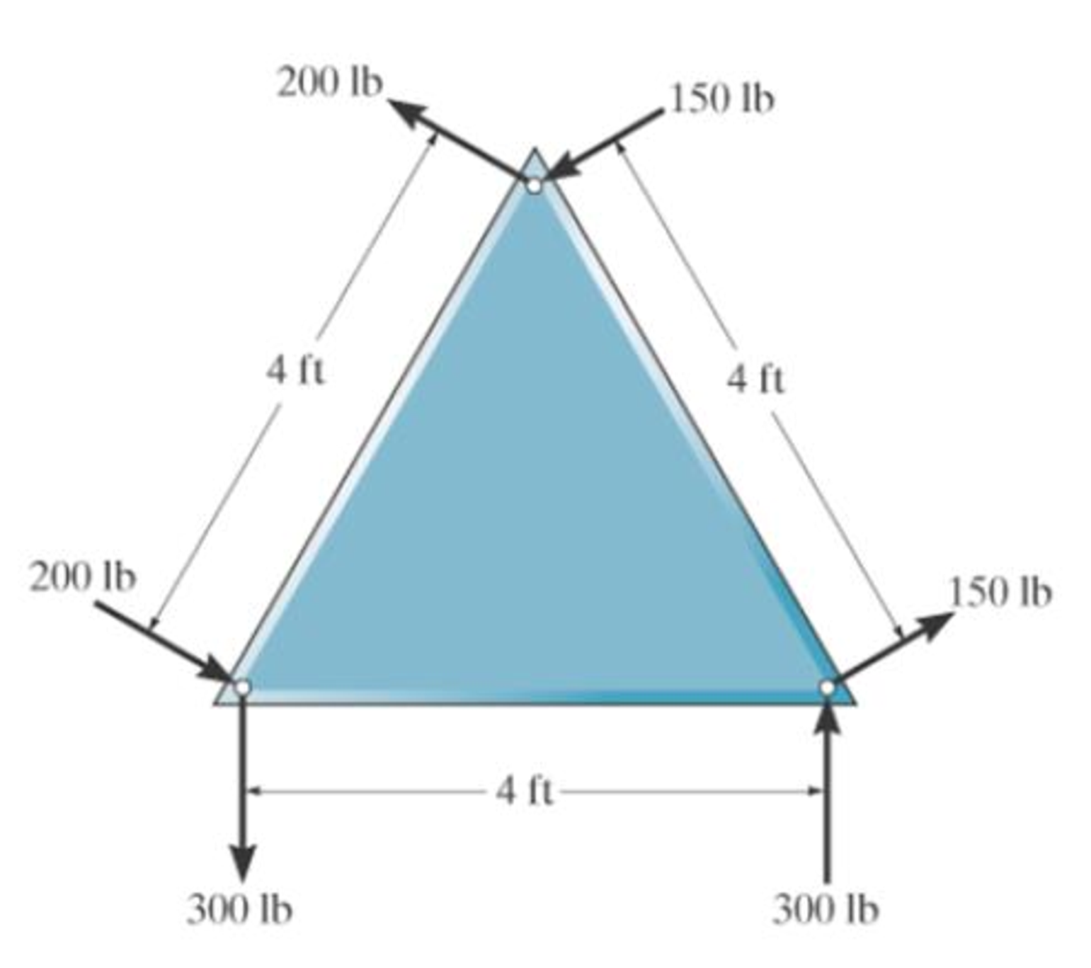
Chapter 4.6, Problem 20FP
F4–20. Determine the resultant couple moment acting on the triangular plate.
Expert Solution & Answer

Learn your wayIncludes step-by-step video

schedule02:27
Students have asked these similar questions
For Problems 5–19 through 5–28, design a crank-rocker mechanism with a time ratio of Q, throw angle of (Δθ4)max, and time per cycle of t. Use either the graphical or analytical method. Specify the link lengths L1, L2, L3, L4, and the crank speed.
Q = 1; (Δθ4)max = 78°; t = 1.2s.
3) find the required fillet welds size if the allowable
shear stress is 9.4 kN/m² for the figure below.
Calls
Ans: h=5.64 mm
T
=
حاجة
، منطقة
نصف القوة
250
190mm
450 mm
F= 30 KN
そのに青
-F₂= 10 KN
F2
a problem existed at the stocking stations of a mini-load AS/RS (automated storage and retrieval system) of a leading electronics manufacturer (Fig.1). At these stations, operators fill the bin delivered by the crane with material arriving in a tote over a roller conveyor. The conveyor was designed at such a height that it was impossible to reach the hooks comfortably even with the tote extended. Furthermore, cost consideration came into the picture and the conveyor height was not reduced. Instead, a step stool was considered to enable the stocker to reach the moving hooks comfortably. The height of the hooks from the floor is 280.2 cm (AD). The tote length is 54.9 cm. The projection of tote length and arm reach, CB = 66.1 cm. a) What anthropometric design principles would you follow to respectively calculate height, length, and width of the step to make it usable to a large number of people? b) What is the minimum height (EF) of the step with no shoe allowance? c) What is the minimum…
Chapter 4 Solutions
Engineering Mechanics: Statics Plus Mastering Engineering with Pearson eText -- Access Card Package (14th Edition) (Hibbeler, The Engineering Mechanics: Statics & Dynamics Series, 14th Edition)
Ch. 4.4 - P41. In each case, determine the moment of the...Ch. 4.4 - P42. In each case, set up the determinant to find...Ch. 4.4 - F41. Determine the moment of the force about point...Ch. 4.4 - F42. Determine the moment of the force about point...Ch. 4.4 - F43. Determine the moment of the force about point...Ch. 4.4 - Neglect the thickness of the member.Ch. 4.4 - F45. Determine the moment of the force about point...Ch. 4.4 - F46. Determine the moment of the force about point...Ch. 4.4 - F47. Determine the resultant moment produced by...Ch. 4.4 - F48. Determine the resultant moment produced by...
Ch. 4.4 - F49. Determine the resultant moment produced by...Ch. 4.4 - Express the result as a Cartesian vector.Ch. 4.4 - Express the result as a Cartesian vector.Ch. 4.4 - Express the result as a Cartesian vector.Ch. 4.4 - If A, B, and D are given vectors, prove the...Ch. 4.4 - Prove the triple scalar product identity A (B C)...Ch. 4.4 - Given the three nonzero vectors A, B and C, show...Ch. 4.4 - Determine the moment about point A of each of the...Ch. 4.4 - Determine the moment about point B of each of the...Ch. 4.4 - Find the moment of each force about point A and...Ch. 4.4 - Determine the moment of each of the three forces...Ch. 4.4 - Determine the moment of each of the three forces...Ch. 4.4 - Take FB = 40 lb, FC = 50 lb. Probs. 49/10Ch. 4.4 - If FB = 30 lb and FC = 45 lb, determine the...Ch. 4.4 - What is this moment?Ch. 4.4 - If x = 10 m, determine the position of the boom...Ch. 4.4 - What is the moment of this force about point B....Ch. 4.4 - Determine the moment of this force about point O....Ch. 4.4 - Determine the moment of each force about A. Which...Ch. 4.4 - If the man at B exerts a force of P = 30 lb on his...Ch. 4.4 - The mechanic reads the torque on the scale at B....Ch. 4.4 - Determine the torque (moment) MP that the applied...Ch. 4.4 - The tongs are used to grip the ends of the...Ch. 4.4 - The handle of the hammer is subjected to the force...Ch. 4.4 - In order to pull out the nail at B, the force F...Ch. 4.4 - The purpose of the fusee is to increase the...Ch. 4.4 - The tower crane is used to hoist the 2-Mg load...Ch. 4.4 - The tower crane is used to hoist a 2-Mg load...Ch. 4.4 - If the 1500-lb boom AB, the 200-lb cage BCD, and...Ch. 4.4 - If the 1500-lb boom AB, the 200-lb cage BCD, and...Ch. 4.4 - Determine the moment of the force F about point O....Ch. 4.4 - Express the result as a Cartesian vector.Ch. 4.4 - The force F = {400i 100j 700k} lb acts at the...Ch. 4.4 - The force F = {400i 100j 700k} lb acts at the end...Ch. 4.4 - Determine the moment of the force F about point P....Ch. 4.4 - The pipe assembly is subjected to the force of F =...Ch. 4.4 - The pipe assembly is subjected to the force of F =...Ch. 4.4 - Determine the moment of the force of F = 600 N...Ch. 4.4 - Determine the smallest force F that must be...Ch. 4.4 - Determine the coordinate direction angles , , of...Ch. 4.4 - Determine the moment of force F about point O. The...Ch. 4.4 - Determine the moment of the force F about the door...Ch. 4.4 - Determine the moment of the force F about the door...Ch. 4.4 - Determine the smallest force F that must be...Ch. 4.4 - Determine the smallest force F that must be...Ch. 4.4 - A 20-N horizontal force is applied perpendicular...Ch. 4.4 - The pipe assembly is subjected to the 80-N force....Ch. 4.4 - The pipe assembly is subjected to the 80-N force....Ch. 4.4 - A force F = {6i 2j + 1k}kN produces a moment of...Ch. 4.4 - The force F = {6i + 8j + 10k}N creates a moment...Ch. 4.4 - A force F having a magnitude of F = 100N acts...Ch. 4.4 - Force F acts perpendicular to the inclined plane....Ch. 4.4 - Force F acts perpendicular to the inclined plane....Ch. 4.4 - Strut AB of the 1-m-diameter hatch door exerts a...Ch. 4.4 - Using a ring collar, the 75-N force can act in the...Ch. 4.5 - P43. In each case, determine the resultant moment...Ch. 4.5 - P44. In each case, set up the determinant needed...Ch. 4.5 - F413. Determine the magnitude of the moment of the...Ch. 4.5 - F414. Determine the magnitude of the moment of the...Ch. 4.5 - Prob. 15FPCh. 4.5 - F416. Determine the magnitude of the moment of the...Ch. 4.5 - Express the result as a Cartesian vector.Ch. 4.5 - Prob. 18FPCh. 4.5 - The lug nut on the wheel of the automobile is to...Ch. 4.5 - Solve Prob. 4-52 if the cheater pipe AB is slipped...Ch. 4.5 - The A-frame is being hoisted into an upright...Ch. 4.5 - The A-frame is being hoisted into an upright...Ch. 4.5 - Determine the magnitude of the moments of the...Ch. 4.5 - Determine the moment of this force F about an axis...Ch. 4.5 - The board is used to hold the end of a four-way...Ch. 4.5 - The board is used to hold the end of a four-way...Ch. 4.5 - The A-frame is being hoisted into an upright...Ch. 4.5 - Determine the magnitude of the moment of the force...Ch. 4.5 - Determine the magnitude of the moment of the force...Ch. 4.5 - Determine the magnitude of the moment of the force...Ch. 4.5 - A horizontal force of F = {50i} N is applied...Ch. 4.5 - Determine the magnitude of the horizontal force F...Ch. 4.5 - The force of F = 30 N acts on the bracket as...Ch. 4.6 - F419. Determine the resultant couple moment acting...Ch. 4.6 - F420. Determine the resultant couple moment acting...Ch. 4.6 - Determine the magnitude of F so that the resultant...Ch. 4.6 - Determine the couple moment acting on the beam.Ch. 4.6 - Determine the resultant couple moment acting on...Ch. 4.6 - Determine the couple moment acting on the pipe...Ch. 4.6 - A clockwise couple M = 5 N m is resisted by the...Ch. 4.6 - A twist of 4 N m is applied to the handle of the...Ch. 4.6 - If the resultant couple of the three couples...Ch. 4.6 - Two couples act on the beam. If F = 125 lb,...Ch. 4.6 - Two couples act on the beam. Determine the...Ch. 4.6 - Determine the magnitude of the couple forces F so...Ch. 4.6 - The ends of the triangular plate are subjected to...Ch. 4.6 - The man tries to open the valve by applying the...Ch. 4.6 - If the valve can be opened with a couple moment of...Ch. 4.6 - Determine the magnitude of F so that the resultant...Ch. 4.6 - Two couples act on the beam as shown. If F = 150...Ch. 4.6 - Two couples act on the beam as shown. Determine...Ch. 4.6 - Two couples act on the frame. If the resultant...Ch. 4.6 - Two couples act on the frame. If d = 4 ft...Ch. 4.6 - Two couples act on the frame. If d = 4 ft,...Ch. 4.6 - Express the moment of the couple acting on the...Ch. 4.6 - If M1 = 180 lb ft, M2 = 90 lb ft, and M3 = 120...Ch. 4.6 - Determine the magnitudes of couple moments M1, M2,...Ch. 4.6 - The gears are subjected to the couple moments...Ch. 4.6 - Prob. 86PCh. 4.6 - Determine the resultant couple moment of the two...Ch. 4.6 - Express the moment of the couple acting on the...Ch. 4.6 - In order to turn over the frame, a couple moment...Ch. 4.6 - Express the moment of the couple acting on the...Ch. 4.6 - If the couple moment acting on the pipe has a...Ch. 4.6 - If F = 80 N, determine the magnitude and...Ch. 4.6 - If the magnitude of the couple moment acting on...Ch. 4.6 - Express the moment of the couple acting on the rod...Ch. 4.6 - If F1 = 100 N, F2 = 120 N, and F3 = 80 N,...Ch. 4.6 - Prob. 96PCh. 4.7 - P45. In each case, determine the x and y...Ch. 4.7 - Replace the leading system by an equivalent...Ch. 4.7 - Prob. 26FPCh. 4.7 - Replace the loading system by an equivalent...Ch. 4.7 - Replace the loading system by an equivalent...Ch. 4.7 - Replace the loading system by an equivalent...Ch. 4.7 - Replace the loading system by an equivalent...Ch. 4.7 - Replace the force system by an equivalent...Ch. 4.7 - Replace the force system by an equivalent...Ch. 4.7 - Replace the force system acting on the beam by an...Ch. 4.7 - Replace the force system acting on the beam by an...Ch. 4.7 - Replace the loading system acting on the beam by...Ch. 4.7 - Replace the loading system acting on the post by...Ch. 4.7 - Replace the loading system acting on the post by...Ch. 4.7 - Replace the force system acting on the post by a...Ch. 4.7 - Replace the force system acting on the frame by an...Ch. 4.7 - The forces F1 = {4i + 2j 3k) kN and F2 = {3i 4j...Ch. 4.7 - A biomechanical model of the lumbar region of the...Ch. 4.7 - Replace the force system by an equivalent...Ch. 4.7 - Replace the loading by an equivalent resultant...Ch. 4.7 - Replace the force of F = 80 N acting on the pipe...Ch. 4.7 - The belt passing over the pulley is subjected to...Ch. 4.7 - The belt passing over the pulley is subjected to...Ch. 4.8 - P46. In each case, determine the x and y...Ch. 4.8 - P47. In each case, determine the resultant force...Ch. 4.8 - Replace the loading system by an equivalent...Ch. 4.8 - Replace the loading system by an equivalent...Ch. 4.8 - Replace the loading system by an equivalent...Ch. 4.8 - Replace the loading system by an equivalent...Ch. 4.8 - Replace the loading shown by an equivalent single...Ch. 4.8 - Replace the loading shown by an equivalent single...Ch. 4.8 - The weights of the various components of the truck...Ch. 4.8 - The weights of the various components of the truck...Ch. 4.8 - Prob. 115PCh. 4.8 - Prob. 116PCh. 4.8 - Replace the loading acting on the beam by a single...Ch. 4.8 - Replace the loading acting on the beam by a single...Ch. 4.8 - Replace the loading on the frame by a single...Ch. 4.8 - Replace the loading on the frame by a single...Ch. 4.8 - Replace the loading on the frame by a single...Ch. 4.8 - Replace the force system acting on the post by a...Ch. 4.8 - Replace the force system acting on the post by a...Ch. 4.8 - Replace the parallel force system acting on the...Ch. 4.8 - Replace the force and couple system acting on the...Ch. 4.8 - Replace the force and couple system acting on the...Ch. 4.8 - Prob. 127PCh. 4.8 - Determine the magnitudes of FA and FB so that the...Ch. 4.8 - The tube supports the four parallel forces....Ch. 4.8 - The building slab is subjected to four parallel...Ch. 4.8 - The building slab is subjected to four parallel...Ch. 4.8 - If FA= 40 kN and FB = 35 kN, determine the...Ch. 4.8 - Prob. 133PCh. 4.8 - Replace the two wrenches and the force, acting on...Ch. 4.8 - Replace the force system by a wrench and specify...Ch. 4.8 - Replace the five forces acting on the plate by a...Ch. 4.8 - Replace the three forces acting on the plate by a...Ch. 4.9 - Determine the resultant force and specify where it...Ch. 4.9 - Determine the resultant force and specify where it...Ch. 4.9 - Determine the resultant force and specify where it...Ch. 4.9 - Determine the resultant force and specify where it...Ch. 4.9 - Determine the resultant force and specify where it...Ch. 4.9 - Determine the resultant force and specify where it...Ch. 4.9 - Replace the loading by an equivalent resultant...Ch. 4.9 - Replace the distributed loading with an equivalent...Ch. 4.9 - Replace the loading by an equivalent resultant...Ch. 4.9 - Currently eighty-five percent of all neck injuries...Ch. 4.9 - Replace the distributed loading by an equivalent...Ch. 4.9 - Replace this loading by an equivalent resultant...Ch. 4.9 - The distribution of soil loading on the bottom of...Ch. 4.9 - Replace the loading by an equivalent resultant...Ch. 4.9 - Replace the distributed loading by an equivalent...Ch. 4.9 - Determine the length b of the triangular load and...Ch. 4.9 - The form is used to cast a concrete wall having a...Ch. 4.9 - Prob. 149PCh. 4.9 - Replace the loading by an equivalent force and...Ch. 4.9 - Prob. 151PCh. 4.9 - Replace the loading by an equivalent resultant...Ch. 4.9 - Replace the leading by a single resultant force,...Ch. 4.9 - Replace the distributed loading by an equivalent...Ch. 4.9 - Prob. 155PCh. 4.9 - Determine the length b of the triangular load and...Ch. 4.9 - Determine the equivalent resultant force and...Ch. 4.9 - Determine the magnitude of the equivalent...Ch. 4.9 - The distributed load acts on the shaft as shown....Ch. 4.9 - Replace the distributed loading with an equivalent...Ch. 4.9 - Prob. 161PCh. 4.9 - Wet concrete exerts a pressure distribution along...Ch. 4.9 - and mass center at G. If the maximum moment that...Ch. 4.9 - R42. Replace the force F having a magnitude of F =...Ch. 4.9 - Determine the moment of this force about the...Ch. 4.9 - Determine the magnitude of the couple forces so...Ch. 4.9 - Prob. 5RPCh. 4.9 - R46. Replace the force system acting on the frame...Ch. 4.9 - Determine the equivalent resultant force and...Ch. 4.9 - R48. Replace the distributed loading by an...
Additional Engineering Textbook Solutions
Find more solutions based on key concepts
What is denormalization?
Database Concepts (8th Edition)
Roman Numerals Write a program that prompts the user to enter a number within the range of 1 through 10. The pr...
Starting Out with Java: From Control Structures through Data Structures (4th Edition) (What's New in Computer Science)
Fill in the blanks in each of the following statements: A relation that has no partial functional dependencies ...
Modern Database Management
Suppose a small company has five employees and is planning to increase the number to six. Moreover, suppose one...
Computer Science: An Overview (13th Edition) (What's New in Computer Science)
What populates the Smalltalk world?
Concepts Of Programming Languages
For the circuit shown, use the node-voltage method to find v1, v2, and i1.
How much power is delivered to the c...
Electric Circuits. (11th Edition)
Knowledge Booster


Learn more about
Need a deep-dive on the concept behind this application? Look no further. Learn more about this topic, mechanical-engineering and related others by exploring similar questions and additional content below.Similar questions
- Qu. 5 Composite materials are becoming more widely used in aircraft industry due to their high strength, low weight and excellent corrosion resistant properties. As an engineer who is given task to design the I beam section of an aircraft (see Figure 7) please, answer the following questions given the material properties in Table 3. Determine the Moduli of Elasticity of Carbon/Epoxy, Aramid/Epoxy, and Boron /Epoxy composites in the longitudinal direction, given that the composites consist of 25 vol% epoxy and 75 vol% fiber. What are the specific moduli of each of these composites? What are the specific strengths (i.e. specific UTS) of each of these composites? What is the final cost of each of these composites?please show all work step by step problems make sure to see formula material sciencearrow_forwardMueh Battery operated train Coll 160,000kg 0.0005 0.15 5m² 1.2kg/m³ CD Af Pair 19 пре neng 0.98 0.9 0.88 Tesla Prated Tesla Trated "wheel ng Joxle 270 kW 440NM 0,45m 20 8.5kg m2 the middle Consider a drive cycle of a 500km trip with 3 stops in Other than the acceleration and deceleration associated with the three stops, the tran maintains constat cruise speed velocity of 324 km/hr. The tran will fast charge at each stop for 15 min at a rate Peharge = 350 kW ΟΙ 15MIN Stop w charging (350kW) (ผม τ (AN GMIJ t 6M 1) HOW MUCH DISTANCE dace is covered DURING THE ACCELERATION TO 324 km/hr? 2) DETERMINE HOW LONG (IN seconds) the tran will BE TRAVELING AT FULL SPEED 2 ? 3) CALCULATE THE NET ENERGY GAW PER STOP etearrow_forwardPlease stop screenshoting ai solution,it always in accurate solve normalarrow_forward
- Research and select any different values for the Ratio of connecting rod length to crank radius from various engine models, then analyze how these changes affect instantaneous velocity and acceleration, presenting your findings visually using graphs.arrow_forwardPb 9) 4.44 bas gnibus& WX 002 grillimatul fred bail (e) For the simply supported I-beam, a load of 1000 lb in center. Find the maximum transverse shear stress. Compare your answer with the approximation obtained by dividing the shear load by the area of the web only with the web considered to extend for the full 8-in depth. - 3½ in. 12 bas in 0% to tolerabib tormi no grived in. 8 in. 38 in. 12 ½ in.arrow_forwardPb 12) 4.61 Draw the Mohr circle for the stresses experienced by the surface of an internally pressurized steel tube that is subject to the tangential and axial stresses in the outer surface of 45 ksi and 30 ksi, respectively, and a torsional stress of 18 ksi. yx 18 45 30arrow_forward
- Pb 8) 4.39 For the C-clamp shown, what force F can be exerted by the screw if the maximum tensile stress in the clamp is to be limited to 30 ksi? F 2 in. სის 3436 16 13 blos 0101 alos12 nodus 121A (s 3 in. in. 16 in. 16 web leonas OFF elson yollA (d 016 (& d of bolow-bloo ai 15912 020112LA sue) vilisub 22 bal.90 Swman a bris ctxibasqqA) laste is tools?arrow_forwardQuiz/An eccentrically loaded bracket is welded to the support as shown in Figure below. The load is static. The weld size for weld w1 is h1 = 6mm, for w2 h2 = 5mm, and for w3 is h3 =5.5 mm. Determine the safety factor (S.f) for the welds. F=22 kN. Use an AWS Electrode type (E90xx). 140 S Find the centroid I want university professor solutions O REDMI NOTE 8 PRO CAI QUAD CAMERA 101.15 Farrow_forwardPb 6) 4.31 do = 25 mm 4.31 What bending moment is required to produce a maximum normal stress of 400 MPa: (a) In a straight round rod of 40-mm diameter? (b) In a straight square rod, 40 mm on a side (with bending about the X axis as shown for a rectangular section in Appendix B-2)?arrow_forward
- Pb 13) 4.73 Find the maximum value of stress at the hole and semicircular notch. 45000 N 50 mm 100 mm 15 mm 25 mm 45000 Narrow_forwardPb 11) 4.53 Consider the 1-in solid round shaft supported by self-aligning bearings at A and B. Attached to the shaft are two chain sprockets that are loaded as shown. Treat this as a static loading problem and identify the specific shat location subjected to the most severe state of stress and make a Mohr circle representation of this stress state. 1-in.-dia. shaft 500 lb 2 in. 1000 lb 3 in. 3 in.arrow_forwardPb 5) 4.19 Estimate the torque required to produce a maximum shear stress of 570 MPa in a hollow shaft having an inner diameter of 20 mm and an outer diameter of 25 mm. d; = 20 mm T d = 25 mm Tmax = 570 MPaarrow_forward
arrow_back_ios
SEE MORE QUESTIONS
arrow_forward_ios
Recommended textbooks for you
 International Edition---engineering Mechanics: St...Mechanical EngineeringISBN:9781305501607Author:Andrew Pytel And Jaan KiusalaasPublisher:CENGAGE L
International Edition---engineering Mechanics: St...
Mechanical Engineering
ISBN:9781305501607
Author:Andrew Pytel And Jaan Kiusalaas
Publisher:CENGAGE L
How to balance a see saw using moments example problem; Author: Engineer4Free;https://www.youtube.com/watch?v=d7tX37j-iHU;License: Standard Youtube License