
Engineering Mechanics: Statics Plus Mastering Engineering with Pearson eText -- Access Card Package (14th Edition) (Hibbeler, The Engineering Mechanics: Statics & Dynamics Series, 14th Edition)
14th Edition
ISBN: 9780134160689
Author: Russell C. Hibbeler
Publisher: PEARSON
expand_more
expand_more
format_list_bulleted
Concept explainers
Videos
Textbook Question
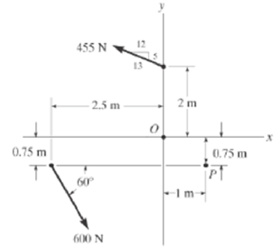
Chapter 4.7, Problem 97P
Replace the force system by an equivalent resultant force and couple moment at point O.
Expert Solution & Answer
Want to see the full answer?
Check out a sample textbook solution
Students have asked these similar questions
I have Euler parameters that describe the orientation of N relative to Q, e = -0.7071*n3, e4 = 0.7071. I have Euler parameters that describe the orientation of U relative to N, e = -1/sqrt(3)*n1, e4 = sqrt(2/3). After using euler parameter rule of successive rotations, I get euler parameters that describe the orientation of U relative to Q, e = -0.4082*n1 - 0.4082*n2 - 0.5774*n3. I need euler parameters that describe the orientation of U relative to Q in vector basis of q instead of n. How do I get that?
Describe at least 4 processes in engineering where control charts are (or should be) applied
Describe at least two (2) processes where control charts are (or should be) applied.
Chapter 4 Solutions
Engineering Mechanics: Statics Plus Mastering Engineering with Pearson eText -- Access Card Package (14th Edition) (Hibbeler, The Engineering Mechanics: Statics & Dynamics Series, 14th Edition)
Ch. 4.4 - P41. In each case, determine the moment of the...Ch. 4.4 - P42. In each case, set up the determinant to find...Ch. 4.4 - F41. Determine the moment of the force about point...Ch. 4.4 - F42. Determine the moment of the force about point...Ch. 4.4 - F43. Determine the moment of the force about point...Ch. 4.4 - Neglect the thickness of the member.Ch. 4.4 - F45. Determine the moment of the force about point...Ch. 4.4 - F46. Determine the moment of the force about point...Ch. 4.4 - F47. Determine the resultant moment produced by...Ch. 4.4 - F48. Determine the resultant moment produced by...
Ch. 4.4 - F49. Determine the resultant moment produced by...Ch. 4.4 - Express the result as a Cartesian vector.Ch. 4.4 - Express the result as a Cartesian vector.Ch. 4.4 - Express the result as a Cartesian vector.Ch. 4.4 - If A, B, and D are given vectors, prove the...Ch. 4.4 - Prove the triple scalar product identity A (B C)...Ch. 4.4 - Given the three nonzero vectors A, B and C, show...Ch. 4.4 - Determine the moment about point A of each of the...Ch. 4.4 - Determine the moment about point B of each of the...Ch. 4.4 - Find the moment of each force about point A and...Ch. 4.4 - Determine the moment of each of the three forces...Ch. 4.4 - Determine the moment of each of the three forces...Ch. 4.4 - Take FB = 40 lb, FC = 50 lb. Probs. 49/10Ch. 4.4 - If FB = 30 lb and FC = 45 lb, determine the...Ch. 4.4 - What is this moment?Ch. 4.4 - If x = 10 m, determine the position of the boom...Ch. 4.4 - What is the moment of this force about point B....Ch. 4.4 - Determine the moment of this force about point O....Ch. 4.4 - Determine the moment of each force about A. Which...Ch. 4.4 - If the man at B exerts a force of P = 30 lb on his...Ch. 4.4 - The mechanic reads the torque on the scale at B....Ch. 4.4 - Determine the torque (moment) MP that the applied...Ch. 4.4 - The tongs are used to grip the ends of the...Ch. 4.4 - The handle of the hammer is subjected to the force...Ch. 4.4 - In order to pull out the nail at B, the force F...Ch. 4.4 - The purpose of the fusee is to increase the...Ch. 4.4 - The tower crane is used to hoist the 2-Mg load...Ch. 4.4 - The tower crane is used to hoist a 2-Mg load...Ch. 4.4 - If the 1500-lb boom AB, the 200-lb cage BCD, and...Ch. 4.4 - If the 1500-lb boom AB, the 200-lb cage BCD, and...Ch. 4.4 - Determine the moment of the force F about point O....Ch. 4.4 - Express the result as a Cartesian vector.Ch. 4.4 - The force F = {400i 100j 700k} lb acts at the...Ch. 4.4 - The force F = {400i 100j 700k} lb acts at the end...Ch. 4.4 - Determine the moment of the force F about point P....Ch. 4.4 - The pipe assembly is subjected to the force of F =...Ch. 4.4 - The pipe assembly is subjected to the force of F =...Ch. 4.4 - Determine the moment of the force of F = 600 N...Ch. 4.4 - Determine the smallest force F that must be...Ch. 4.4 - Determine the coordinate direction angles , , of...Ch. 4.4 - Determine the moment of force F about point O. The...Ch. 4.4 - Determine the moment of the force F about the door...Ch. 4.4 - Determine the moment of the force F about the door...Ch. 4.4 - Determine the smallest force F that must be...Ch. 4.4 - Determine the smallest force F that must be...Ch. 4.4 - A 20-N horizontal force is applied perpendicular...Ch. 4.4 - The pipe assembly is subjected to the 80-N force....Ch. 4.4 - The pipe assembly is subjected to the 80-N force....Ch. 4.4 - A force F = {6i 2j + 1k}kN produces a moment of...Ch. 4.4 - The force F = {6i + 8j + 10k}N creates a moment...Ch. 4.4 - A force F having a magnitude of F = 100N acts...Ch. 4.4 - Force F acts perpendicular to the inclined plane....Ch. 4.4 - Force F acts perpendicular to the inclined plane....Ch. 4.4 - Strut AB of the 1-m-diameter hatch door exerts a...Ch. 4.4 - Using a ring collar, the 75-N force can act in the...Ch. 4.5 - P43. In each case, determine the resultant moment...Ch. 4.5 - P44. In each case, set up the determinant needed...Ch. 4.5 - F413. Determine the magnitude of the moment of the...Ch. 4.5 - F414. Determine the magnitude of the moment of the...Ch. 4.5 - Prob. 15FPCh. 4.5 - F416. Determine the magnitude of the moment of the...Ch. 4.5 - Express the result as a Cartesian vector.Ch. 4.5 - Prob. 18FPCh. 4.5 - The lug nut on the wheel of the automobile is to...Ch. 4.5 - Solve Prob. 4-52 if the cheater pipe AB is slipped...Ch. 4.5 - The A-frame is being hoisted into an upright...Ch. 4.5 - The A-frame is being hoisted into an upright...Ch. 4.5 - Determine the magnitude of the moments of the...Ch. 4.5 - Determine the moment of this force F about an axis...Ch. 4.5 - The board is used to hold the end of a four-way...Ch. 4.5 - The board is used to hold the end of a four-way...Ch. 4.5 - The A-frame is being hoisted into an upright...Ch. 4.5 - Determine the magnitude of the moment of the force...Ch. 4.5 - Determine the magnitude of the moment of the force...Ch. 4.5 - Determine the magnitude of the moment of the force...Ch. 4.5 - A horizontal force of F = {50i} N is applied...Ch. 4.5 - Determine the magnitude of the horizontal force F...Ch. 4.5 - The force of F = 30 N acts on the bracket as...Ch. 4.6 - F419. Determine the resultant couple moment acting...Ch. 4.6 - F420. Determine the resultant couple moment acting...Ch. 4.6 - Determine the magnitude of F so that the resultant...Ch. 4.6 - Determine the couple moment acting on the beam.Ch. 4.6 - Determine the resultant couple moment acting on...Ch. 4.6 - Determine the couple moment acting on the pipe...Ch. 4.6 - A clockwise couple M = 5 N m is resisted by the...Ch. 4.6 - A twist of 4 N m is applied to the handle of the...Ch. 4.6 - If the resultant couple of the three couples...Ch. 4.6 - Two couples act on the beam. If F = 125 lb,...Ch. 4.6 - Two couples act on the beam. Determine the...Ch. 4.6 - Determine the magnitude of the couple forces F so...Ch. 4.6 - The ends of the triangular plate are subjected to...Ch. 4.6 - The man tries to open the valve by applying the...Ch. 4.6 - If the valve can be opened with a couple moment of...Ch. 4.6 - Determine the magnitude of F so that the resultant...Ch. 4.6 - Two couples act on the beam as shown. If F = 150...Ch. 4.6 - Two couples act on the beam as shown. Determine...Ch. 4.6 - Two couples act on the frame. If the resultant...Ch. 4.6 - Two couples act on the frame. If d = 4 ft...Ch. 4.6 - Two couples act on the frame. If d = 4 ft,...Ch. 4.6 - Express the moment of the couple acting on the...Ch. 4.6 - If M1 = 180 lb ft, M2 = 90 lb ft, and M3 = 120...Ch. 4.6 - Determine the magnitudes of couple moments M1, M2,...Ch. 4.6 - The gears are subjected to the couple moments...Ch. 4.6 - Prob. 86PCh. 4.6 - Determine the resultant couple moment of the two...Ch. 4.6 - Express the moment of the couple acting on the...Ch. 4.6 - In order to turn over the frame, a couple moment...Ch. 4.6 - Express the moment of the couple acting on the...Ch. 4.6 - If the couple moment acting on the pipe has a...Ch. 4.6 - If F = 80 N, determine the magnitude and...Ch. 4.6 - If the magnitude of the couple moment acting on...Ch. 4.6 - Express the moment of the couple acting on the rod...Ch. 4.6 - If F1 = 100 N, F2 = 120 N, and F3 = 80 N,...Ch. 4.6 - Prob. 96PCh. 4.7 - P45. In each case, determine the x and y...Ch. 4.7 - Replace the leading system by an equivalent...Ch. 4.7 - Prob. 26FPCh. 4.7 - Replace the loading system by an equivalent...Ch. 4.7 - Replace the loading system by an equivalent...Ch. 4.7 - Replace the loading system by an equivalent...Ch. 4.7 - Replace the loading system by an equivalent...Ch. 4.7 - Replace the force system by an equivalent...Ch. 4.7 - Replace the force system by an equivalent...Ch. 4.7 - Replace the force system acting on the beam by an...Ch. 4.7 - Replace the force system acting on the beam by an...Ch. 4.7 - Replace the loading system acting on the beam by...Ch. 4.7 - Replace the loading system acting on the post by...Ch. 4.7 - Replace the loading system acting on the post by...Ch. 4.7 - Replace the force system acting on the post by a...Ch. 4.7 - Replace the force system acting on the frame by an...Ch. 4.7 - The forces F1 = {4i + 2j 3k) kN and F2 = {3i 4j...Ch. 4.7 - A biomechanical model of the lumbar region of the...Ch. 4.7 - Replace the force system by an equivalent...Ch. 4.7 - Replace the loading by an equivalent resultant...Ch. 4.7 - Replace the force of F = 80 N acting on the pipe...Ch. 4.7 - The belt passing over the pulley is subjected to...Ch. 4.7 - The belt passing over the pulley is subjected to...Ch. 4.8 - P46. In each case, determine the x and y...Ch. 4.8 - P47. In each case, determine the resultant force...Ch. 4.8 - Replace the loading system by an equivalent...Ch. 4.8 - Replace the loading system by an equivalent...Ch. 4.8 - Replace the loading system by an equivalent...Ch. 4.8 - Replace the loading system by an equivalent...Ch. 4.8 - Replace the loading shown by an equivalent single...Ch. 4.8 - Replace the loading shown by an equivalent single...Ch. 4.8 - The weights of the various components of the truck...Ch. 4.8 - The weights of the various components of the truck...Ch. 4.8 - Prob. 115PCh. 4.8 - Prob. 116PCh. 4.8 - Replace the loading acting on the beam by a single...Ch. 4.8 - Replace the loading acting on the beam by a single...Ch. 4.8 - Replace the loading on the frame by a single...Ch. 4.8 - Replace the loading on the frame by a single...Ch. 4.8 - Replace the loading on the frame by a single...Ch. 4.8 - Replace the force system acting on the post by a...Ch. 4.8 - Replace the force system acting on the post by a...Ch. 4.8 - Replace the parallel force system acting on the...Ch. 4.8 - Replace the force and couple system acting on the...Ch. 4.8 - Replace the force and couple system acting on the...Ch. 4.8 - Prob. 127PCh. 4.8 - Determine the magnitudes of FA and FB so that the...Ch. 4.8 - The tube supports the four parallel forces....Ch. 4.8 - The building slab is subjected to four parallel...Ch. 4.8 - The building slab is subjected to four parallel...Ch. 4.8 - If FA= 40 kN and FB = 35 kN, determine the...Ch. 4.8 - Prob. 133PCh. 4.8 - Replace the two wrenches and the force, acting on...Ch. 4.8 - Replace the force system by a wrench and specify...Ch. 4.8 - Replace the five forces acting on the plate by a...Ch. 4.8 - Replace the three forces acting on the plate by a...Ch. 4.9 - Determine the resultant force and specify where it...Ch. 4.9 - Determine the resultant force and specify where it...Ch. 4.9 - Determine the resultant force and specify where it...Ch. 4.9 - Determine the resultant force and specify where it...Ch. 4.9 - Determine the resultant force and specify where it...Ch. 4.9 - Determine the resultant force and specify where it...Ch. 4.9 - Replace the loading by an equivalent resultant...Ch. 4.9 - Replace the distributed loading with an equivalent...Ch. 4.9 - Replace the loading by an equivalent resultant...Ch. 4.9 - Currently eighty-five percent of all neck injuries...Ch. 4.9 - Replace the distributed loading by an equivalent...Ch. 4.9 - Replace this loading by an equivalent resultant...Ch. 4.9 - The distribution of soil loading on the bottom of...Ch. 4.9 - Replace the loading by an equivalent resultant...Ch. 4.9 - Replace the distributed loading by an equivalent...Ch. 4.9 - Determine the length b of the triangular load and...Ch. 4.9 - The form is used to cast a concrete wall having a...Ch. 4.9 - Prob. 149PCh. 4.9 - Replace the loading by an equivalent force and...Ch. 4.9 - Prob. 151PCh. 4.9 - Replace the loading by an equivalent resultant...Ch. 4.9 - Replace the leading by a single resultant force,...Ch. 4.9 - Replace the distributed loading by an equivalent...Ch. 4.9 - Prob. 155PCh. 4.9 - Determine the length b of the triangular load and...Ch. 4.9 - Determine the equivalent resultant force and...Ch. 4.9 - Determine the magnitude of the equivalent...Ch. 4.9 - The distributed load acts on the shaft as shown....Ch. 4.9 - Replace the distributed loading with an equivalent...Ch. 4.9 - Prob. 161PCh. 4.9 - Wet concrete exerts a pressure distribution along...Ch. 4.9 - and mass center at G. If the maximum moment that...Ch. 4.9 - R42. Replace the force F having a magnitude of F =...Ch. 4.9 - Determine the moment of this force about the...Ch. 4.9 - Determine the magnitude of the couple forces so...Ch. 4.9 - Prob. 5RPCh. 4.9 - R46. Replace the force system acting on the frame...Ch. 4.9 - Determine the equivalent resultant force and...Ch. 4.9 - R48. Replace the distributed loading by an...
Knowledge Booster


Learn more about
Need a deep-dive on the concept behind this application? Look no further. Learn more about this topic, mechanical-engineering and related others by exploring similar questions and additional content below.Similar questions
- Problem 3: A cube-shaped spacecraft is in a circular Earth orbit. Let N (n,) be inertial and the spacecraft is denoted S (ŝ₁). The spacecraft is described such that ¯½º = J ŝ₁ŝ₁ + J ŝ₂§₂ + J §¸Ŝ3 Location of the spacecraft in the orbit is determined by the orbit-fixed unit vectors ê, that are oriented by the angle (Qt), where is a constant angular rate. 52 €3 3> 2t 55 Λ Из At the instant when Qt = 90°, the spacecraft S is oriented relative to the orbit such that 8₁ = 0° Space-three 1-2-3 angles 0₂ = 60° and ES = $₂ rad/s 0₁ = 135° (a) At this instant, determine the direction cosine matrix that describes the orientation of the spacecraft with respect to the inertial frame N.arrow_forwardThis problem illustrates that the factor of safety for a machine element depends on the particular point selected for analysis. Here you are to compute factors of safety, based upon the distortion-energy theory, for stress elements at A and B of the member shown in the figure. This bar is made of AISI 1006 cold-drawn steel and is loaded by the forces F = 1.100 kN, P = 8.00 kN, and T = 50.00 N-m. Given: Sy = 280 MPa. B -100 mm- 15-mm D. a) Determine the value of the axial stress at point B. b) Determine the value of the shear stress at point B. c) Determine the value of the Von Mises stress at point B. P Farrow_forwardA piston-cylinder device initially contains 0.08 m^3 of nitrogen gas at 130 kPa and 170°C. The nitrogen is expanded to a pressure of 80 kPa via isentropic expansion. Determine the final temperature and the boundary work done by the system during this process.arrow_forward
- A Carnot (ideal) heat pump is to be used to heat a house and maintain it at 22°C in winter. On a day when the average outdoor temperature remains at about 0°C, the house is estimated to lose heat at a rate of 65,000 kJ/h. If the heat pump consumes 6 kW of power while operating, determine: (a) how long the heat pump ran on that day (b) the total heating costs, assuming an average price of 11¢/kWh for electricity (c) the heating cost for the same day if an 85% efficient electric furnace is used instead of a heat pump.arrow_forwardFrom the information in the image, I needed to find the orientation of U relative to Q in vector basis q_hat. I transformed the euler angle/axis representation to euler parameters. Then I got its conjugate in order to get the euler parameter in N frame relative to Q. The problem gave the euler angle/axis representation in Q frame relative to N, so I needed to find the conjugate. Then I used the euler parameter rule of successive rotation to find the final euler parameters that describe the orientation of U relative to Q. However that orientation is in n_hat which is the intermediate frame. How do I get the final result in q_hat?arrow_forwardA proposed method of power generation involves collecting and storing solar energy in large artificial lakes a few meters deep, called solar ponds. Solar energy is absorbed by all parts of the pond, and the water temperature rises everywhere. The top part of the pond, however, loses much of the heat it absorbs to the atmosphere, and as a result, the cool surface water serves as insulation for the bottom part of the pond and helps trap the energy there. Usually, salt is planted at the bottom of the pond to prevent the rise of this hot water to the top. A heat engine that uses an organic fluid, such as alcohol, as the working fluid can be operated between the top and the bottom portions of the pond. If the water temperature is 27°C near the surface and 72°C near the bottom of the pond, determine the maximum thermal efficiency that this power plant can have. Treat the cycle as an ideal heat engine. Would a heat engine operating under these temperature conditions (27°C and 72°C) be…arrow_forward
- A standard Carnot heat engine cycle is executed in a closed system between the temperature limits of 320 and 1350 K, with air as the working fluid. The pressures before and after the isothermal compression are 150 and 300 kPa, respectively. Sketch the TS diagram for this cycle. If the net work output per cycle is 0.75 kJ, determine the efficiency of the cycle and the heat transfer to the air (working fluid) per cycle.arrow_forwardPROBLEM 10: A sleeve in the form of a circular tube of length L is Nut placed around a bolt and fitted between washers at each end. The nut is then turned until it is just snug. Use material properties as follows: For the sleeve, as = 21 x 106/°C and Es = 100 GPa Washer Bolt ·L· Sleeve Bolt head For the bolt, αB = 10 × 10-6/°C and EB = 200 GPa. 1. Calculate the temperature rise that is required to produce a compressive stress of 25 MPa in the sleeve.arrow_forwardThis problem illustrates that the factor of safety for a machine element depends on the particular point selected for analysis. Here you are to compute factors of safety, based upon the distortion-energy theory, for stress elements at A and B of the member shown in the figure. This bar is made of AISI 1006 cold-drawn steel and is loaded by the forces F = 1.100 kN, P = 8.00 kN, and T = 50.00 N·m. Given: Sy = 280 MPa. B -100 mm- 15-mm D. a) What is the value of the axial stress at point A? b)What is the value of the shear stress at point A? c)Determine the value of the Von Mises stress at point A. P Farrow_forward
- The three steel wires, each of cross-sectional area 0.05 in2, support the weight W. Theirunstressed lengths are 74.98 ft, 74.99 ft, and 75.00 ft. Use E = 29 x 106 psi.1. Find the stress (psi) in the longest wire if W = 1500 lb.2. Determine the stress in the shortest wire if W = 500 lb ANSWERS: 6130 psi; 6930 psiarrow_forward1: The concrete column is reinforced using four steel reinforcing rods, each having a diameter of 18 mm. Determine the stress in the concrete and the steel if the column is subjected to an axial load of 800 kN. Est = 200 GPa, Ec = 25 GPa. Complete fbd.arrow_forward5: As shown, two aluminum rods AB and BC, hinged to rigid supports, arepinned together at B to carry a vertical load P = 6000 lb. If each rod has a crosssectional area of 0.60 in2 and E = 10 x 106 psi. Use α = θ = 30⁰. Calculate the change in length (in) of rod AB and indicate if it elongates orshortens. Calculate the vertical displacement of B (in) and horizontal displacement of B (in). Complete fbd.arrow_forward
arrow_back_ios
SEE MORE QUESTIONS
arrow_forward_ios
Recommended textbooks for you
 International Edition---engineering Mechanics: St...Mechanical EngineeringISBN:9781305501607Author:Andrew Pytel And Jaan KiusalaasPublisher:CENGAGE L
International Edition---engineering Mechanics: St...
Mechanical Engineering
ISBN:9781305501607
Author:Andrew Pytel And Jaan Kiusalaas
Publisher:CENGAGE L
Types Of loads - Engineering Mechanics | Abhishek Explained; Author: Prime Course;https://www.youtube.com/watch?v=4JVoL9wb5yM;License: Standard YouTube License, CC-BY