Concept explainers
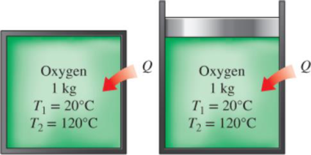
1 kg of oxygen is heated from 20 to 120°C. Determine the amount of heat transfer required when this is done during a (a) constant-volume process and (b) isobaric process.
FIGURE P4–62

The amount of heat transfers to constant-volume process.
The amount of heat transfers to isobaric process.
Answer to Problem 62P
The amount of heat transfers to constant-volume process is
The amount of heat transfers to isobaric process is
Explanation of Solution
Write the general expression for the energy balance equation.
Here, the total energy entering the system is
Simplify Equation (I) and write energy balance during a constant-volume process.
Here, the heat to be transfer into the system is
Take the oxygen as the system.
Substitute
Here, the mass of oxygen is
Rewrite the Equation (I) and write energy balance during a constant-pressure process.
Here, the heat to be transfer into the constant-pressure process is
Since, the quasi-equilibrium process during a constant pressure
Determine the change in temperature.
Here, the initial temperature oxygen is
Write the expression for linear interpolation method.
Here, the result of constant-pressure of specific heat is
Conclusion:
Substitute
Substitute
From above calculation the constant-pressure of specific heat is
Substitute
From above calculation the constant-volume of specific heat is
From the Table A-2b “Ideal-gas specific heats of various common gases”, obtain the value of constant-volume specific heat of air at 300 K temperature as
Substitute
Thus, the amount of heat transfers to constant-volume process is
Substitute
Thus, the amount of heat transfers to isobaric process is
Want to see more full solutions like this?
Chapter 4 Solutions
THERMODYNAMICS (LL)-W/ACCESS >CUSTOM<
- The differential equation of a cruise control system is provided by the following equation: Find the closed loop transfer function with respect to the reference velocity (vr) . a. Find the poles of the closed loop transfer function for different values of K. How does the poles move as you change K? b. Find the step response for different values of K and plot in MATLAB. What can you observe? c. For the given transfer function, find tp, ts, tr, Mp . Plot the resulting step response. G(s) = 40/(s^2 + 4s + 40)arrow_forwardAuto Controls Perform the partial fraction expansion of the following transfer function and find the impulse response: G(s) = (s/2 + 5/3) / (s^2 + 4s + 6) G(s) =( 6s^2 + 50) / (s+3)(s^2 +4)arrow_forwardStudy Area Document Sharing User Settings mylabmastering.pearson.com Access Pearson P Pearson MyLab and Mastering The 150-lb skater passes point A with a speed of 6 ft/s. (Figure 1) Figure 1 of 1 Part A P Course Home b My Questions | bartleby Determine his speed when he reaches point B. Neglect friction. Express your answer to three significant figures and include the appropriate units. με ? VB = Value Units Submit Request Answer Part B Determine the normal force exerted on him by the track at this point. Express your answer to three significant figures and include the appropriate units. ☐ о Α NB = Value Units Submit Request Answer Provide Feedback ? ■Review Next >arrow_forward
- mylabmastering.pearson.com Access Pearson P Pearson MyLab and Mastering P Course Home b My Questions | bartleby Study Area Document Sharing User Settings The 100-kg crate is subjected to the forces shown. The crate is originally at rest. The coefficient of kinetic friction between the crate and the surface is μk = 0.2. (Figure 1) Part A Determine the distance it slides in order to attain a speed of 8.1 m/s. Express your answer to three significant figures and include the appropriate units. Figure 500 N 1 of 1 Α S = Value Units Submit Request Answer Provide Feedback ? ■Review Next >arrow_forwardThe differential equation of a DC motor can be described by the following equation Find the transfer function between the applied voltage ( Va)and the motor speed (thetadot m). What is the steady state speed of the motor after a voltage (Va = 10V) has been applied. Find the transfer function between the applied voltage (Va) and the shaft angle (thetadot m) .arrow_forwardStudy Area Document Sharing User Settings Access Pearson mylabmastering.pearson.com P Pearson MyLab and Mastering The crash cushion for a highway barrier consists of a nest of barrels filled with an impact-absorbing material. The barrier stopping force is measured versus the vehicle penetration into the barrier. (Figure 1) Part A P Course Home b My Questions | bartleby Review Determine the distance a car having a weight of 4000 lb will penetrate the barrier if it is originally traveling at 55 ft/s when it strikes the first barrel. Express your answer to three significant figures and include the appropriate units. Figure 1 of 1 36 μΑ S = Value Units Submit Request Answer Provide Feedback ? Next >arrow_forward
- Study Area Document Sharing User Settings mylabmastering.pearson.com Access Pearson P Pearson MyLab and Mastering Part A P Course Home b My Questions | bartleby ■Review The sports car has a mass of 2.5 Mg and accelerates at 6 m/s², starting from rest. (Figure 1) If the drag resistance on the car due to the wind is FD = (10v) N, where v is the velocity in m/s, determine the power supplied to the engine when t = 5 s. The engine has a running efficiency of € = 0.66. Express your answer to three significant figures and include the appropriate units. Figure 1 of 1 о Α ? P = Value Units Submit Request Answer Return to Assignment Provide Feedbackarrow_forwardAccess Pearson Study Area mylabmastering.pearson.com P Pearson MyLab and Mastering Document Sharing User Settings The car in (Figure 1) having a mass of 2 Mg is originally traveling at 2 m/s. Assume 0 = 22°. Figure 1 of 1 Part A P Course Home b My Questions | bartleby ■Review Determine the distance it must be towed by a force F = 4 kN in order to attain a speed of 6 m/s. Neglect friction and the mass of the wheels. Express your answer to three significant figures and include the appropriate units. Α ? S = Value Units Submit Request Answer Provide Feedback Next >arrow_forwardDerive the Laplace transform of the following functions. Use the definition of Laplace transform. f(t)=sin4t and f(t)=cos2t Auto Controlsarrow_forward
- Study Area Document Sharing User Settings Access Pearson P Pearson MyLab and Mastering Marbles having a mass of 5 g fall from rest at A through the glass tube and accumulate in the can at C. (Figure 1) Figure Aarrow_forwardVC Vc B S TDC -BDC S TQ Tp = Pg A (asne) [1+ % CUSA] At what position (in degrees after top dead center) would you want the peak pressure of combustion to occur to create the maximum torque on the crankshaft? For a 100mm piston digimeter acting on a connecting. rod with a length of 80mm use the equation above to calculate the torque (NIM) on the crankshaft at this crank position for an engine that develops a peak pressure of 135 bararrow_forwardAccess Pearson P Pearson MyLab and Mastering Study Area Document Sharing User Settings The man having a weight of 180 lb is able to run up a 18-ft-high flight of stairs shiwn in (Figure 1) in 4 s. Figure 1 of 1 R mylabmastering.pearson.com Part A P Course Home b My Questions | bartleby Determine the power generated. Express your answer in horsepower to three significant figures. ΜΕ ΑΣΦ. Η vec P = Submit Request Answer Part B ? hp How long would a 100-W light bulb have to burn to expend the same amount of energy? Express your answer to three significant figures and include the appropriate units. HÅ ? t = Value Units Submit Request Answer Provide Feedback Review Next >arrow_forward
 Elements Of ElectromagneticsMechanical EngineeringISBN:9780190698614Author:Sadiku, Matthew N. O.Publisher:Oxford University Press
 Mechanics of Materials (10th Edition)Mechanical EngineeringISBN:9780134319650Author:Russell C. HibbelerPublisher:PEARSON
 Thermodynamics: An Engineering ApproachMechanical EngineeringISBN:9781259822674Author:Yunus A. Cengel Dr., Michael A. BolesPublisher:McGraw-Hill Education
 Control Systems EngineeringMechanical EngineeringISBN:9781118170519Author:Norman S. NisePublisher:WILEY
 Mechanics of Materials (MindTap Course List)Mechanical EngineeringISBN:9781337093347Author:Barry J. Goodno, James M. GerePublisher:Cengage Learning
 Engineering Mechanics: StaticsMechanical EngineeringISBN:9781118807330Author:James L. Meriam, L. G. Kraige, J. N. BoltonPublisher:WILEY


