
MECHANICS OF MATERIALS
11th Edition
ISBN: 9780137605521
Author: HIBBELER
Publisher: RENT PEARS
expand_more
expand_more
format_list_bulleted
Concept explainers
Videos
Textbook Question
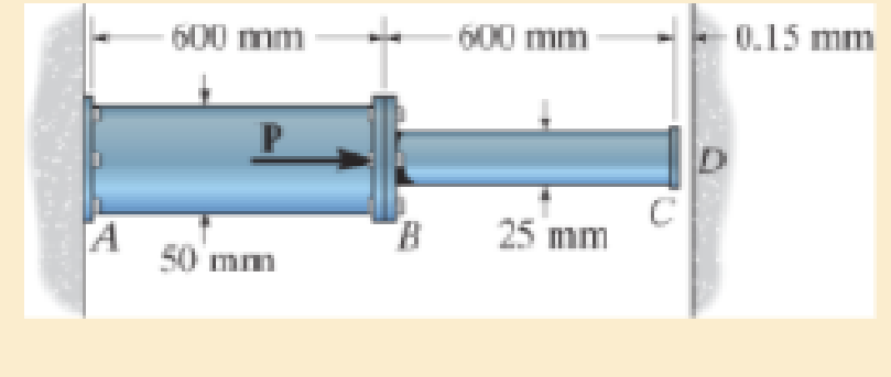
Chapter 4.5, Problem 46P
If the gap between C and the rigid wall at D is initially 0.15 mm, determine the support reactions at A and D when the force P = 200 kN is applied. The assembly is made of solid A-36 steel cylinders.
Prob. 4–46
Expert Solution & Answer

Learn your wayIncludes step-by-step video

schedule05:11
Students have asked these similar questions
A triangular distributed load of max intensity w =460 N/m
acts on beam AB. The beam is supported by a pin at A and
member CD, which is connected by pins at C and D
respectively. Determine the reaction forces at A and C.
Enter your answers in Cartesian components. Assume the
masses of both beam AB and member CD are negligible.
cc 040
BY NC SA
2016 Eric Davishahl
W
A
C
D
-a-
B
Ул
-b-
x
Values for dimensions on the figure are given in the following
table. Note the figure may not be to scale.
Variable Value
α
5.4 m
b
8.64 m
C
3.24 m
The reaction at A is A =
i+
ĴN.
λ =
i+
Ĵ N.
The reaction at C is C =
56
Clamps like the one shown are commonly used in
woodworking applications. This clamp has the dimensions
given in the table below the figure, and its jaws are
mm thick (in the direction perpendicular to the plane of the
picture).
a.) The screws of the clamp are adjusted so that there is a
uniform pressure of P = 150 kPa being applied to the
workpieces by the jaws. Determine the force carried in each
screw. Hint: the uniform pressure can be modeled in 2-D as a
uniform distributed load with intensity w = Pt (units of
N/m) acting over the length of contact between the jaw and
the workpiece.
b.) Determine the minimum vertical force (parallel to the
jaws) required to pull either one of the workpieces out of the
clamp jaws. Use a coefficient of static friction between all
contacting surfaces of μs = 0.56 and the same clamping
pressure given for part (a).
2013 Michael Swanbom
A
B
C
a
Values for dimensions on the figure are given in the following
table. Note the figure may not be to scale.…
Determine the force in each member of the space truss given
F=5 kN. Use positive to indicate tension and negative to
indicate compression.
F
E
Z
-2 m.
B
3 m
C
5 m
3 m
A
-4 m.
AB
=
KN
FAC =
FAD =
KN
KN
KN
FBC =
KN
FBD
FBE
=
=
KN
F
Chapter 4 Solutions
MECHANICS OF MATERIALS
Ch. 4.2 - The 20-mm-diameter A-36 steel rod is subjected to...Ch. 4.2 - Segments AB and CD of the assembly are solid...Ch. 4.2 - The 30-mm-diameter A992 steel rod is subjected to...Ch. 4.2 - If the 20-mm-diameter rod is made of A-36 steel...Ch. 4.2 - The 20-mm-diameter 2014-T6 aluminum rod is...Ch. 4.2 - The 20-mm-diameter 2014-T6 aluminum rod is...Ch. 4.2 - The copper shaft is subjected to the axial loads...Ch. 4.2 - The A-36 steel rod is subjected to the loading...Ch. 4.2 - The A-36 steel rod is subjected to the loading...Ch. 4.2 - The A-36 steel drill shaft of an oil well extends...
Ch. 4.2 - Prob. 8PCh. 4.2 - The post is made of Douglas fir and has a diameter...Ch. 4.2 - The post is made of Douglas fir and has a diameter...Ch. 4.2 - The coupling rod is subjected to a force of 5 kip....Ch. 4.2 - The pipe is stuck in the ground so that when it is...Ch. 4.2 - The assembly consists of three titanium...Ch. 4.2 - The assembly consists of two rigid bars that are...Ch. 4.2 - The truss consists of three members, each made...Ch. 4.2 - Solve Prob. 426 when the load P acts vertically...Ch. 4.2 - The ball is truncated at its ends and is used to...Ch. 4.5 - The column is constructed from high-strength...Ch. 4.5 - The column is constructed from high-strength...Ch. 4.5 - The A-36 steel pipe has a 6061-T6 aluminum core....Ch. 4.5 - The 304 stainless steel post A has a diameter of...Ch. 4.5 - The 304 stainless steel post A is surrounded by a...Ch. 4.5 - The 10-mm-diameter steel bolt is surrounded by a...Ch. 4.5 - The rigid beam is supported by the three suspender...Ch. 4.5 - The bolt AB has a diameter of 20 mm and passes...Ch. 4.5 - If the gap between C and the rigid wall at D is...Ch. 4.5 - The support consists of a solid red brass C83400...Ch. 4.5 - Prob. 55PCh. 4.5 - The three A-36 steel wires each have a diameter of...Ch. 4.5 - The A-36 steel wires AB and AD each have a...Ch. 4.5 - The assembly consists of two posts AB and CD each...Ch. 4.5 - The assembly consists of two posts AB and CD each...Ch. 4.5 - The assembly consists of two posts AB and CD each...Ch. 4.5 - The wheel is subjected to a force of 18 kN from...Ch. 4.6 - The C83400-red-brass rod AB and 2014-T6- aluminum...Ch. 4.6 - The assembly has the diameters and material...Ch. 4.6 - Prob. 72PCh. 4.6 - Prob. 77PCh. 4.6 - Prob. 80PCh. 4.6 - The 50-mm-diameter cylinder is made from Am...Ch. 4.6 - The 50-mm-diameter cylinder is made from Am...Ch. 4.6 - The metal strap has a thickness t and width w and...Ch. 4.9 - Determine the maximum normal stress developed in...Ch. 4.9 - If the allowable normal stress for the bar is...Ch. 4.9 - Prob. 89PCh. 4.9 - The A-36 steel plate has a thickness of 12 mm. If...Ch. 4.9 - Determine the maximum axial force P that can be...Ch. 4.9 - Determine the maximum normal stress developed in...Ch. 4.9 - The member is to be made from a steel plate that...Ch. 4.9 - Prob. 96PCh. 4.9 - The bar has a cross-sectional area of 0.5 in2 and...Ch. 4.9 - The distributed loading is applied to the rigid...Ch. 4.9 - The distributed loading is applied to the rigid...Ch. 4.9 - The rigid lever arm is supported by two A-36 steel...Ch. 4.9 - The rigid lever arm is supported by two A-36 steel...Ch. 4.9 - The wire BC has a diameter of 0.125 in. and the...Ch. 4.9 - Prob. 104PCh. 4.9 - Prob. 106PCh. 4 - The assembly consists of two A992 steel bolts AB...Ch. 4 - The assembly shown consists of two A992 steel...Ch. 4 - The rods each have the same 25-mm diameter and...Ch. 4 - Two A992 steel pipes, each having a...Ch. 4 - The force P is applied to the bar, which is made...Ch. 4 - The 2014-T6 aluminum rod has a diameter of 0.5 in....Ch. 4 - The 2014-T6 aluminum rod has a diameter of 0.5 in....Ch. 4 - The rigid link is supported by a pin at A and two...Ch. 4 - The joint is made from three A992 steel plates...
Additional Engineering Textbook Solutions
Find more solutions based on key concepts
Define a class called TicTacToe. An object of type TicTacToe is a single game of tic-tac-toe. Store the game be...
Java: An Introduction to Problem Solving and Programming (8th Edition)
Write a loop that counts the number of space characters that appear in the String object str.
Starting Out with Java: From Control Structures through Data Structures (4th Edition) (What's New in Computer Science)
The Bridgeport vertical-spindle milling machine is perhaps the single most popular machine tool. Virtually ever...
Degarmo's Materials And Processes In Manufacturing
ICA 8-13
A golden bar of metal (5 centimeters [cm] by 18 cent meters [cm] by 4 centimeters [cm]) being transpor...
Thinking Like an Engineer: An Active Learning Approach (4th Edition)
2-1 List the five types of measurements that form the
basis of traditional ptane surveying-
Elementary Surveying: An Introduction To Geomatics (15th Edition)
Write an SQL statement to display the breed, type, and DOB for all pets having the type Dog and the breed Std. ...
Database Concepts (8th Edition)
Knowledge Booster


Learn more about
Need a deep-dive on the concept behind this application? Look no further. Learn more about this topic, mechanical-engineering and related others by exploring similar questions and additional content below.Similar questions
- A short brass cyclinder (denisty=8530 kg/m^3, cp=0.389 kJ/kgK, k=110 W/mK, and alpha=3.39*10^-5 m^2/s) of diameter 4 cm and height 20 cm is initially at uniform temperature of 150 degrees C. The cylinder is now placed in atmospheric air at 20 degrees C, where heat transfer takes place by convection with a heat transfer coefficent of 40 W/m^2K. Calculate (a) the center temp of the cylinder, (b) the center temp of the top surface of the cylinder, and (c) the total heat transfer from the cylinder 15 min after the start of the cooling. Solve this problem using the analytical one term approximation method. (Answer: (a) 45.7C, (b)45.3C, (c)87.2 kJ)arrow_forwardA short brass cyclinder (denisty=8530 kg/m^3, cp=0.389 kJ/kgK, k=110 W/mK, and alpha=3.39*10^-5 m^2/s) of diameter 4 cm and height 20 cm is initially at uniform temperature of 150 degrees C. The cylinder is now placed in atmospheric air at 20 degrees C, where heat transfer takes place by convection with a heat transfer coefficent of 40 W/m^2K. Calculate (a) the center temp of the cylinder, (b) the center temp of the top surface of the cylinder, and (c) the total heat transfer from the cylinder 15 min after the start of the cooling. Solve this problem using the analytical one term approximation method.arrow_forwardA 6 cm high rectangular ice block (k=2.22 W/mK, and alpha=0.124*10^-7 m^2/s) initially at -18 degrees C is placed on a table on its square base 4 cm by 4cm in size in a room at 18 degrees C. The heat transfer coefficent on the exposed surfaces of the ice block is 12 W/m^2K. Disregarding any heat transfer from the base to the table, determine how long it will be before the ice block starts melting. Where on the ice block will the first liquid droplets appear? Solve this problem using the analytical one-term approximation method.arrow_forward
- Consider a piece of steel undergoing a decarburization process at 925 degrees C. the mass diffusivity of carbon in steel at 925 degrees C is 1*10^-7 cm^2/s. Determine the depth below the surface of the steel at which the concentration of carbon is reduced to 40 percent from its initial value as a result of the decarburization process for (a) an hour and (b) 10 hours. Assume the concnetration of carbon at the surface is zero throughout the decarburization process.arrow_forwardPlease do not rely too much on chatgpt, because its answer may be wrong. Please consider it carefully and give your own answer. You can borrow ideas from gpt, but please do not believe its answer.Very very grateful! Please do not copy other's work,i will be very very grateful!!arrow_forwardMultiple Choice Circle the best answer to each statement. 1. Which geometry attribute deviation(s) can be limited with a profile of a surface tolerance? A. Location B. Orientation C. Form D. All of the above 2. A true profile may be defined with: A. Basic radii B. Basic angles C. Formulas D. All of the above 3. Which modifier may be applied to the profile tolerance value? A B C. D. All of the above 4. The default tolerance zone for a profile tolerance is: A. Non-uniform B. Unilateral C. Bilateral equal distribution D. Bilateral-unequal distribution 5. An advantage of using a profile tolerance in place of a coordinate tolerance is: A. A bonus tolerance is permitted. B. A datum feature sequence may be specified C. A profile tolerance always controls size D. All of the above 6. The shape of the tolerance zone for a profile tolerance is: A. Two parallel planes B. The same as the true profile of the toleranced surface C. Equal bilateral D. Cylindrical when the diameter symbol is speci- fied…arrow_forward
- One thousand kg/h of a (50-50 wt%) acetone-in-water solution is to be extracted at 25C in a continuous, countercurrent system with pure 1,1,2-trichloroethane to obtain a raffinate containing 10 wt% acetone. Using the following equilibrium data, determine with an equilateral-triangle diagram: a- the minimum flow rate of solvent; b- the number of stages required for a solvent rate equal to 1.5 times minimum, and composition of each streamleaving each stage. c- Repeat the calculation of (a) and (b) if the solvent used has purity 93wt% (4wr% acetone, 3wt% water impurities) acetone water 1,1,2-trichloroethane Raffinate. Weight Extract. Weight 0.6 0.13 0.27 Fraction Acetone Fraction Acetone 0.5 0.04 0.46 0.44 0.56 0.4 0.03 0.57 0.29 0.40 0.3 0.02 0.68 0.12 0.18 0.2 0.015 0.785 0.0 0.0 0.1 0.01 0.89 0.55 0.35 0.1 0.5 0.43 0.07 0.4 0.57 0.03 0.3 0.68 0.02 0.2 0.79 0.01 0.1 0.895 0.005arrow_forward2500 kg/hr of (20-80) nicotine water solution is to be extracted with benzene containing 0.5% nicotine in the 1st and 2ed stages while the 3rd stage is free of nicotine. Cross- current operation is used with different amounts of solvent for each stages 2000kg/hr in the 1st stage, 2300 kg/hr in the 2nd stage, 2600 kg/hr in the 3rd, determine: - a- The final raffinate concentration and % extraction. b- b- The minimum amount of solvent required for counter-current operation if the minimum concentration will be reduced to 5% in the outlet raffinate. Equilibrium data Wt % Nicotine in water Wt % Nicotine in benzene 0 4 16 25 0 4 21 30arrow_forwardQuiz/An eccentrically loaded bracket is welded to the support as shown in Figure below. The load is static. The weld size for weld w1 is h1=6mm, for w2 h2 5mm, and for w3 is h3 -5.5 mm. Determine the safety factor (S.f) for the welds. F=22 kN. Use an AWS Electrode type (E90xx). 140 101.15 REDMI NOTE 8 PRO AI QUAD CAMERA Farrow_forward
- (read image)arrow_forwardProblem 3.30 A piston-cylinder device contains 0.85 kg of refrigerant- 134a at -10°C. The piston that is free to move has a mass of 12 kg and a diameter of 25 cm. The local atmospheric pressure is 100 kPa. Now, heat is transferred to refrigerant-134a until the temperature is 15°C. Determine (a) the final pressure, (b) the change in the volume of the refrigerant, and (c) the change in the enthalpy of the refrigerant-134a. please show Al work step by steparrow_forwardPart 1 The storage tank contains lubricating oil of specific gravity 0.86 In one inclined side of the tank, there is a 0.48 m diameter circular inspection door, mounted on a horizontal shaft along the centre line of the gate. The oil level in the tank rests 8.8 m above the mounted shaft. (Please refer table 01 for relevant SG, D and h values). Describe the hydrostatic force and centre of pressure with the aid of a free body diagram of the inspection door. Calculate the magnitude of the hydrostatic force and locate the centre of pressure. 45° Estimate the moment that would have to be applied to the shaft to open the gate. Stop B If the oil level raised by 2 m from the current level, calculate the new moment required to open the gate. Figure 01arrow_forward
arrow_back_ios
SEE MORE QUESTIONS
arrow_forward_ios
Recommended textbooks for you
 Elements Of ElectromagneticsMechanical EngineeringISBN:9780190698614Author:Sadiku, Matthew N. O.Publisher:Oxford University Press
 Mechanics of Materials (10th Edition)Mechanical EngineeringISBN:9780134319650Author:Russell C. HibbelerPublisher:PEARSON
 Thermodynamics: An Engineering ApproachMechanical EngineeringISBN:9781259822674Author:Yunus A. Cengel Dr., Michael A. BolesPublisher:McGraw-Hill Education
 Control Systems EngineeringMechanical EngineeringISBN:9781118170519Author:Norman S. NisePublisher:WILEY
 Mechanics of Materials (MindTap Course List)Mechanical EngineeringISBN:9781337093347Author:Barry J. Goodno, James M. GerePublisher:Cengage Learning
 Engineering Mechanics: StaticsMechanical EngineeringISBN:9781118807330Author:James L. Meriam, L. G. Kraige, J. N. BoltonPublisher:WILEY
Elements Of Electromagnetics
Mechanical Engineering
ISBN:9780190698614
Author:Sadiku, Matthew N. O.
Publisher:Oxford University Press
Mechanics of Materials (10th Edition)
Mechanical Engineering
ISBN:9780134319650
Author:Russell C. Hibbeler
Publisher:PEARSON
Thermodynamics: An Engineering Approach
Mechanical Engineering
ISBN:9781259822674
Author:Yunus A. Cengel Dr., Michael A. Boles
Publisher:McGraw-Hill Education
Control Systems Engineering
Mechanical Engineering
ISBN:9781118170519
Author:Norman S. Nise
Publisher:WILEY
Mechanics of Materials (MindTap Course List)
Mechanical Engineering
ISBN:9781337093347
Author:Barry J. Goodno, James M. Gere
Publisher:Cengage Learning
Engineering Mechanics: Statics
Mechanical Engineering
ISBN:9781118807330
Author:James L. Meriam, L. G. Kraige, J. N. Bolton
Publisher:WILEY
EVERYTHING on Axial Loading Normal Stress in 10 MINUTES - Mechanics of Materials; Author: Less Boring Lectures;https://www.youtube.com/watch?v=jQ-fNqZWrNg;License: Standard YouTube License, CC-BY