
Concept explainers
Videos
A truss can be supported in the eight different ways shown A connections consist of smooth pins, rollers, or short links. For case, answer the questions listed in Prob. 4.59, and, wherever possible, compute the reactions, assuming that the magnitude force P is 12 kips.
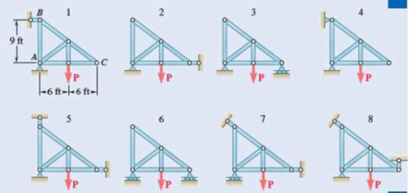
Fig. P4.60
(a)
Find whether the plate is completely, partially, or improperly constrained.
Answer to Problem 4.60P
The plate in figure 1 is
The plate figure 2 is
The plate figure 3 is
The plate figure 4 is
The plate figure 5 is
The plate figure 6 is
The plate figure 7 is
The plate figure 8 is
Explanation of Solution
Given information:
The magnitude of the force P is 12 kips.
Calculation:
Figure 1:
Show the free-body diagram of the Figure 1.
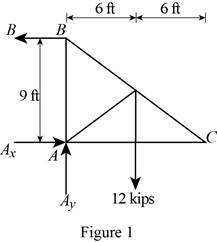
The three reactions in the plate behave like non-concurrent and non-parallel force system.
The plate in figure 1 is
Figure 2:
Show the free-body diagram of the Figure 2.
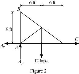
The three reactions in the plate behave like concurrent force system.
The plate figure 2 is
Figure 3:
Show the free-body diagram of the Figure 3.
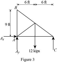
The three reactions in the plate behave like non-concurrent and non-parallel force system.
The plate figure 3 is
Figure 4:
Show the free-body diagram of the Figure 4.
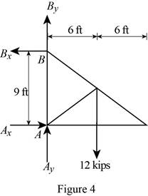
The four reactions in the plate behave like non-concurrent and non-parallel force system.
The plate figure 4 is
Figure 5:
Show the free-body diagram of the Figure 5.
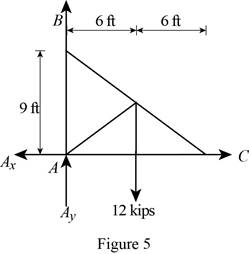
The four reactions in the plate behave like concurrent force system.
The plate figure 5 is
Figure 6:
Show the free-body diagram of the Figure 6.
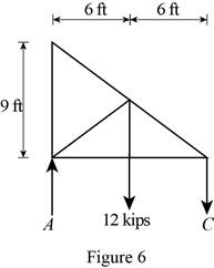
The two reactions in the plate behave like concurrent force system.
The plate figure 6 is
Figure 7:
Show the free-body diagram of the Figure 7.
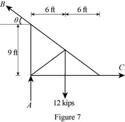
The three reactions in the plate behave like non-concurrent and non-parallel force system.
The plate figure 7 is
Figure 8:
Show the free-body diagram of the Figure 8.
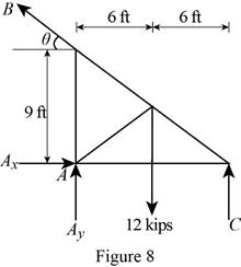
The four reactions in the plate behave like non-concurrent and non-parallel force system.
The plate figure 8 is
(b)
Find whether the reactions are statically determinate or indeterminate.
Answer to Problem 4.60P
The reactions in figure 1 is
The reactions in figure 2 is
The reactions in figure 3 is
The reactions in figure 4 is
The reactions in figure 5 is
The reactions in figure 6 is
The reactions in figure 7 is
The reactions in figure 8 is
Explanation of Solution
Refer Figure 1:
The equilibrium equations are;
The equilibrium equations are enough to determine the unknown reactions.
The reactions in figure 1 is
Refer Figure 2:
The equilibrium equations are;
The equilibrium equations are enough to determine the unknown reactions.
But the plate is improperly constrained and the plate is not in equilibrium.
The reactions in figure 2 is
Refer Figure 3:
The equilibrium equations are;
The equilibrium equations are enough to determine the unknown reactions.
The reactions in figure 3 is
Refer Figure 4:
The equilibrium equations are;
The equilibrium equations are not enough to determine the unknown reactions.
The reactions in figure 4 is
Refer Figure 5:
The equilibrium equations are;
The equilibrium equations are enough to determine the unknown reactions.
But the plate is improperly constrained and the plate is not in equilibrium.
The reactions in figure 5 is
Refer Figure 6:
The equilibrium equations are;
The equilibrium equations are enough to determine the unknown reactions.
The reactions in figure 6 is
Refer Figure 7:
The equilibrium equations are;
The equilibrium equations are enough to determine the unknown reactions.
The reactions in figure 7 is
Refer Figure 8:
The equilibrium equations are;
The equilibrium equations are not enough to determine the unknown reactions.
The reactions in figure 8 is
(c)
Find whether the equilibrium of the plate is maintained.
Answer to Problem 4.60P
The reactions in the plate 1 are
The plate 1 is in
The plate 2 is in
The reactions in the plate 3 are
The plate 3 is in
The reactions in the plate 4 are
The plate 4 is in
The plate 5 is in
The reactions in the plate 6 are
The plate 6 is in
The reactions in the plate 7 are
The plate 7 is in
The reactions in the plate 8 are
The plate 8 is in
Explanation of Solution
Refer Figure 1:
The equilibrium equations are;
Take moment about point A.
Resolve the horizontal component of forces.
Resolve the vertical component of forces.
Find the resultant force at A;
Find the angle
Therefore, the reactions in the plate 1 are
The plate 1 is in
Refer Figure 2:
The equilibrium equations are;
The moment about point A is not equal to zero.
The plate 2 is in
Refer Figure 3:
The equilibrium equations are;
Take moment about point A.
Resolve the horizontal component of forces.
Resolve the vertical component of forces.
Therefore, the reactions in the plate 3 are
The plate 3 is in
Refer Figure 4:
The equilibrium equations are;
Take moment about point A.
Resolve the horizontal component of forces.
Resolve the vertical component of forces.
Therefore, the reactions in the plate 4 are
The plate 4 is in
Refer Figure 5:
The equilibrium equations are;
The moment about point A is not equal to zero.
The plate 5 is in
Refer Figure 6:
The equilibrium equations are;
Take moment about point A.
Resolve the vertical component of forces.
Therefore, the reactions in the plate 6 are
The plate 6 is in
Refer Figure 7:
The equilibrium equations are;
Find the angle
Take moment about point A.
Resolve the horizontal component of forces.
Resolve the vertical component of forces.
Therefore, the reactions in the plate 7 are
The plate 7 is in
Refer Figure 8:
The equilibrium equations are;
Take moment about point C.
Therefore, the reactions in the plate 8 are
The plate 8 is in
Want to see more full solutions like this?
Chapter 4 Solutions
Vector Mechanics for Engineers: Statics and Dynamics


- Draw left view of the first orthographic projectionarrow_forwardSketch and Describe a timing diagram for a 2 stroke diesel engine emphasis on the 2 stroke as my last answer explained 4 stroke please include a diagram or sketch.arrow_forwardA 4 ft 200 Ib 1000 Ib.ft C 2 ft 350 Ib - за в 2.5 ft 150 Ib 250 Ib 375 300 Ib Replace the force system acting on the frame. shown in the figure by a resultant force (magnitude and direction), and specify where its line of action intersects member (AB), measured from point (A).arrow_forward
- A continuous flow calorimeter was used to obtain the calorific value of a sample of fuel and the following data collected: Mass of fuel: 2.25 kgInlet water temperature: 11 ° COutlet water temperature 60 ° CQuantity of water: 360 Liters Calorimeter efficiency: 85%Calculate the calorific value of the sample ( kJ / kg ). ive submitted this question twice and have gotten two way different answers. looking for some help thanksarrow_forward15 kg of steel ball bearings at 100 ° C is immersed in 25 kg of water at 20 ° C . Assuming no loss of heat to or from the container, calculate the final temperature of the water after equilibrium has been attained.Specific heat of steel: 0.4857 kJ / kg / ° KSpecific heat of water: 4.187 kJ / kg / ° Karrow_forwardSketch and explain a PV Diagram and a Temperature Entropy Diagram for a 4 stroke diesel enginearrow_forward
- A continuous flow calorimeter was used to obtain the calorific value of a sample of fuel and the following data collected: Mass of fuel: 2.25 kgInlet water temperature: 11 ° COutlet water temperature 60 ° CQuantity of water: 360 Liters Calorimeter efficiency: 85%Calculate the calorific value of the sample ( kJ / kg ).arrow_forwardChapter 12 - Lecture Notes.pptx: (MAE 272-01) (SP25) DY... Scoresarrow_forwardmylabmastering.pearson.com Chapter 12 - Lecture Notes.pptx: (MAE 272-01) (SP25) DY... P Pearson MyLab and Mastering Scoresarrow_forwardanswer the fallowing Brake Specific Fuel Consumption - 0.3 kg/kwh, Mechanical Efficiency- 90% Calorific Value of Fuel -45 MJ/kg. Given these values, find the indicated power, indicated thermal efficiency and brake thermal efficiencyarrow_forwardProblem 6. The circular plate shown rotates about its vertical diameter. At the instant shown, the angular velocity ₁ of the plate is 10 rad/s and is decreasing at the rate of 25 rad/s². The disk lies in the XY plane and Point D of strap CD moves upward. The relative speed u of Point D of strap CD is 1.5 m/s and is decreasing at the rate of 3 m/s². Determine (a) the velocity of D, (b) the acceleration of D. Answers: =0.75 +1.299]-1.732k m/s a=-28.6 +3.03-10.67k m/s² 200 mm x Zarrow_forwardProblem 1. The flywheel A has an angular velocity o 5 rad/s. Link AB is connected via ball and socket joints to the flywheel at A and a slider at B. Find the angular velocity of link AB and the velocity of slider B at this instant. (Partial Answer: @ABN = -2î + 2.25; red Z -1.2 ft C -7 Y -1.5 ft- B 2.0 ftarrow_forwardarrow_back_iosSEE MORE QUESTIONSarrow_forward_iosRecommended textbooks for you
 Elements Of ElectromagneticsMechanical EngineeringISBN:9780190698614Author:Sadiku, Matthew N. O.Publisher:Oxford University Press
 Mechanics of Materials (10th Edition)Mechanical EngineeringISBN:9780134319650Author:Russell C. HibbelerPublisher:PEARSON
 Thermodynamics: An Engineering ApproachMechanical EngineeringISBN:9781259822674Author:Yunus A. Cengel Dr., Michael A. BolesPublisher:McGraw-Hill Education
 Control Systems EngineeringMechanical EngineeringISBN:9781118170519Author:Norman S. NisePublisher:WILEY
 Mechanics of Materials (MindTap Course List)Mechanical EngineeringISBN:9781337093347Author:Barry J. Goodno, James M. GerePublisher:Cengage Learning
 Engineering Mechanics: StaticsMechanical EngineeringISBN:9781118807330Author:James L. Meriam, L. G. Kraige, J. N. BoltonPublisher:WILEY
Elements Of ElectromagneticsMechanical EngineeringISBN:9780190698614Author:Sadiku, Matthew N. O.Publisher:Oxford University PressMechanics of Materials (10th Edition)Mechanical EngineeringISBN:9780134319650Author:Russell C. HibbelerPublisher:PEARSONThermodynamics: An Engineering ApproachMechanical EngineeringISBN:9781259822674Author:Yunus A. Cengel Dr., Michael A. BolesPublisher:McGraw-Hill EducationControl Systems EngineeringMechanical EngineeringISBN:9781118170519Author:Norman S. NisePublisher:WILEYMechanics of Materials (MindTap Course List)Mechanical EngineeringISBN:9781337093347Author:Barry J. Goodno, James M. GerePublisher:Cengage LearningEngineering Mechanics: StaticsMechanical EngineeringISBN:9781118807330Author:James L. Meriam, L. G. Kraige, J. N. BoltonPublisher:WILEY