
Vector Mechanics for Engineers: Statics and Dynamics
12th Edition
ISBN: 9781259638091
Author: Ferdinand P. Beer, E. Russell Johnston Jr., David Mazurek, Phillip J. Cornwell, Brian Self
Publisher: McGraw-Hill Education
expand_more
expand_more
format_list_bulleted
Concept explainers
Videos
Textbook Question
Chapter 4.1, Problem 4.2FBP
A lever AB is hinged at C and attached to a control cable at A. If the lever is subjected to a 75-lb vertical force at B, draw the free-body diagram needed to determine the tension in the cable and the reaction at C.
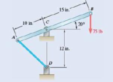
Fig.P4.F2
Expert Solution & Answer
Want to see the full answer?
Check out a sample textbook solution
Students have asked these similar questions
Please answer
Oxygen at 300 kPa and 90°C flowing at an average velocity of 3 m/s is expanded in an adiabatic nozzle. What is the maximum velocity of the oxygen at the outlet of this nozzle when the outlet pressure is 60 kPa? Use the table containing the ideal gas specific heats of various common gases.
The maximum velocity of the oxygen at the outlet of this nozzle is 532.5 Numeric ResponseEdit Unavailable. 532.5 incorrect.m/s.
A container filled with 70 kg of liquid water at 95°C is placed in a 90-m3 room that is initially at 12°C. Thermal equilibrium is established after a while as a result of heat transfer between the water and the air in the room. Assume the room is at the sea level, well sealed, and heavily insulated.
NOTE: This is a multi-part question. Once an answer is submitted, you will be unable to return to this part.
Determine the amount of heat transfer between the water and the air in the room.
The amount of heat transfer between the water and the air in the room is kJ.
A strain gauge rosette that is attached to the surface of a stressed component
gives 3 readings (ɛa = A, b = B, &c = C). If the strain gauge rosette is of the D°
type (indicating the angle between each of the gauges), construct a Mohr's Strain
Circle overleaf. You should assume that gauge A is aligned along the x-axis.
Using the Mohr's Strain Circle calculate the:
(i) principal strains (ε1, 2)?
(ii) principal angles (1, 2)?
You should measure these anticlockwise from the y-axis.
(iii) maximum shear strain in the plane (ymax)?
Chapter 4 Solutions
Vector Mechanics for Engineers: Statics and Dynamics
Ch. 4.1 - Two crates, each of mass 350 kg, are placed as...Ch. 4.1 - A lever AB is hinged at C and attached to a...Ch. 4.1 - A light rod AD is supported by frictionless pegs...Ch. 4.1 - A tension of 20 N is maintained in a tape as it...Ch. 4.1 - A gardener uses a 60 N wheelbarrow to transport a...Ch. 4.1 - The gardener of Prob. 4.1 wishes to transport a...Ch. 4.1 - A 2100-lb tractor is used to lift 900 lb of grave....Ch. 4.1 - For the beam and loading shown, determine (a) the...Ch. 4.1 - A load of lumber of weight W = 25 kN is being...Ch. 4.1 - A load of lumber of weight W = 25 kN is being...
Ch. 4.1 - A hand truck is used to move a compressed-air...Ch. 4.1 - Two external shafts of a gearbox are subject to...Ch. 4.1 - Three loads are applied as shown to a light beam...Ch. 4.1 - The 10-m beam AB rests upon, but is not attached...Ch. 4.1 - The maximum allowable value of each of the...Ch. 4.1 - For the beam of Sample Prob. 4.2, determine the...Ch. 4.1 - The maximum allowable value of each of the...Ch. 4.1 - For the beam and loading shown, determine the...Ch. 4.1 - PROBLEM 4.15 The required tension in cable AB is...Ch. 4.1 - PROBLEM 4.16 Determine the maximum tension that...Ch. 4.1 - Two links AB and DE are connected by a bell crank...Ch. 4.1 - Two links AB and DE are connected by a bell crank...Ch. 4.1 - The bracket BCD is hinged at C and attached to a...Ch. 4.1 - The ladder AB, of length L and weight W, can be...Ch. 4.1 - The ladder AB, of length L and weight W, can be...Ch. 4.1 - A lever AB is hinged at C and attached to a...Ch. 4.1 - 4.23 and 4.24 For each of the plates and loadings...Ch. 4.1 - Prob. 4.24PCh. 4.1 - A rod AB, hinged at A and attached at B to cable...Ch. 4.1 - Prob. 4.26PCh. 4.1 - For the frame and loading shown, determine the...Ch. 4.1 - Determine the reactions at A and C when (a) = 0,...Ch. 4.1 - The spanner shown is used to rotate a shaft. A pin...Ch. 4.1 - The spanner shown is used to rotate a shaft. A pin...Ch. 4.1 - Neglecting friction, determine the tension in...Ch. 4.1 - Fig. P4.31 and P4.32 4.32 Neglecting friction,...Ch. 4.1 - PROBLEM 4.33 A force P of magnitude 90 lb is...Ch. 4.1 - PROBLEM 4.34 Solve Problem 4,33 for a = 6 in,...Ch. 4.1 - Prob. 4.35PCh. 4.1 - PROBLEM 4.36 A light bar AD is suspended from a...Ch. 4.1 - A 160-lb overhead garage door consists of a...Ch. 4.1 - Fig. P4.37 4.38 In Prob. 4.37, determine the...Ch. 4.1 - Prob. 4.39PCh. 4.1 - Fig. P4.39 4.40 Solve Prob. 4.39 when = 30.Ch. 4.1 - The semicircular rod ABCD is maintained in...Ch. 4.1 - Prob. 4.42PCh. 4.1 - The rig shown consists of a 1200-lb horizontal...Ch. 4.1 - Fig. P4.43 4.44 For the rig and crate of Prob....Ch. 4.1 - Prob. 4.45PCh. 4.1 - Knowing that the tension in wire BD is 1300 N,...Ch. 4.1 - Prob. 4.47PCh. 4.1 - Beam AD carries the two 40-lb loads shown. The...Ch. 4.1 - Fig. P4.48 and P4.49 4.49 For the beam and loading...Ch. 4.1 - A traffic-signal pole may be supported in the...Ch. 4.1 - A uniform rod AB with a length of l and weight of...Ch. 4.1 - Rod AD is acted upon by a vertical force P at end...Ch. 4.1 - A slender rod AB with a weigh of W is attached to...Ch. 4.1 - 4.54 and 4.55 A vertical load P is applied at end...Ch. 4.1 - 4.54 and 4.55 A vertical load P is applied at end...Ch. 4.1 - A collar B with a weight of W can move freely...Ch. 4.1 - A 400-lb weight is attached at A to the lever...Ch. 4.1 - A vertical load P is applied at end B of rod BC....Ch. 4.1 - Prob. 4.59PCh. 4.1 - A truss can be supported in the eight different...Ch. 4.2 - A 500-lb cylindrical tank, 8 ft in diameter, is to...Ch. 4.2 - Determine the reactions at A and E when =0.Ch. 4.2 - Determine (a) the value of for which the reaction...Ch. 4.2 - A 12-ft ladder, weighing 40 lb, leans against a...Ch. 4.2 - Determine the reactions at B and C when a = 30 mm.Ch. 4.2 - Determine the reactions at A and E. Fig. P4.66Ch. 4.2 - Determine the reactions at B and D when b = 60 mm....Ch. 4.2 - For the frame and loading shown, determine the...Ch. 4.2 - A 50-kg crate is attached to the trolley-beam...Ch. 4.2 - One end of rod AB rests in the corner A and the...Ch. 4.2 - For the boom and loading shown, determine (a) the...Ch. 4.2 - A 50-lb sign is supported by a pin and bracket at...Ch. 4.2 - Determine the reactions at A and D when = 30.Ch. 4.2 - Determine the reactions at A and D when = 60.Ch. 4.2 - Rod AB is supported by a pin and bracket at A and...Ch. 4.2 - Solve Prob. 4.75, assuming that the 170-N force...Ch. 4.2 - The L-shaped member ACB is supported by a pin and...Ch. 4.2 - Using the method of Sec. 4.2B, solve Prob. 4.22....Ch. 4.2 - Knowing that = 30, determine the reaction (a) at...Ch. 4.2 - Knowing that = 60, determine the reaction (a) at...Ch. 4.2 - Determine the reactions at A and B when = 50....Ch. 4.2 - Determine the reactions at A and B when = 80.Ch. 4.2 - Rod AB is bent into the shape of an arc of circle...Ch. 4.2 - A slender rod of length L is attached to collars...Ch. 4.2 - An 8-kg slender rod of length L is attached to...Ch. 4.2 - Prob. 4.86PCh. 4.2 - A slender rod BC with a length of L and weight W...Ch. 4.2 - A thin ring with a mass of 2 kg and radius r = 140...Ch. 4.2 - A slender rod with a length of L and weight W is...Ch. 4.2 - Fig. P4.89 4.90 Knowing that for the rod of Prob....Ch. 4.3 - Two tape spools are attached to an axle supported...Ch. 4.3 - Prob. 4.6FBPCh. 4.3 - A 20-kg cover for a roof opening is hinged at...Ch. 4.3 - Prob. 4.91PCh. 4.3 - Prob. 4.92PCh. 4.3 - A small winch is used to raise a 120-lb load. Find...Ch. 4.3 - Two transmission belts pass over sheaves welded to...Ch. 4.3 - A 250 400-mm plate of mass 12 kg and a...Ch. 4.3 - Prob. 4.96PCh. 4.3 - The rectangular plate shown weighs 60 lb and is...Ch. 4.3 - A load W is to be placed on the 60-lb plate of...Ch. 4.3 - Prob. 4.99PCh. 4.3 - Prob. 4.100PCh. 4.3 - PROBLEM 4.101 Two steel pipes AB and BC, each...Ch. 4.3 - PROBLEM 4.102 For the pipe assembly of Problem...Ch. 4.3 - PROBLEM 4.103 The 24-lb square plate shown is...Ch. 4.3 - PROBLEM 4.104 The table shown weighs 30 lb and has...Ch. 4.3 - PROBLEM 4.105 A 10-ft boom is acted upon by the...Ch. 4.3 - PROBLEM 4.106 The 6-m pole ABC is acted upon by a...Ch. 4.3 - PROBLEM 4.107 Solve Problem 4.106 for a = 1.5 m....Ch. 4.3 - A 3-m pole is supported by a ball-and-socket joint...Ch. 4.3 - PROBLEM 4.109 A 3-m pole is supported by a...Ch. 4.3 - PROBLEM 4.110 A 7-ft boom is held by a ball and...Ch. 4.3 - PROBLEM 4.111 A 48-in. boom is held by a...Ch. 4.3 - PROBLEM 4.112 Solve Problem 4.111, assuming that...Ch. 4.3 - PROBLEM 4.114 The bent rod ABEF is supported by...Ch. 4.3 - The bent rod ABEF is supported by bearings at C...Ch. 4.3 - The horizontal platform ABCD weighs 60 lb and...Ch. 4.3 - Prob. 4.116PCh. 4.3 - Prob. 4.117PCh. 4.3 - Solve Prob. 4.117, assuming that cable DCE is...Ch. 4.3 - PROBLEM 4.119 Solve Prob. 4.113, assuming that the...Ch. 4.3 - PROBLEM 4.120 Solve Prob. 4.115, assuming that the...Ch. 4.3 - PROBLEM 4.121 The assembly shown is used to...Ch. 4.3 - Prob. 4.122PCh. 4.3 - PROBLEM 4.123 The rigid L-shaped member ABC is...Ch. 4.3 - Solve Prob. 4.123; assuming that cable BD is...Ch. 4.3 - Prob. 4.125PCh. 4.3 - Prob. 4.126PCh. 4.3 - Prob. 4.127PCh. 4.3 - Prob. 4.128PCh. 4.3 - Frame ABCD is supported by a ball-and-socket joint...Ch. 4.3 - Prob. 4.130PCh. 4.3 - The assembly shown consists of an 80-mm rod AF...Ch. 4.3 - Prob. 4.132PCh. 4.3 - The frame ACD is supported by ball-and-socket...Ch. 4.3 - Prob. 4.134PCh. 4.3 - The 8-ft rod AB and the 6-ft rod BC are hinged at...Ch. 4.3 - Solve Prob. 4.135 when h = 10.5 ftCh. 4.3 - Prob. 4.137PCh. 4.3 - Prob. 4.138PCh. 4.3 - Prob. 4.139PCh. 4.3 - Prob. 4.140PCh. 4.3 - Prob. 4.141PCh. 4 - Prob. 4.142RPCh. 4 - 4. 143 The lever BCD is hinged at C and attached...Ch. 4 - Prob. 4.144RPCh. 4 - Neglecting friction and the radius of the pulley,...Ch. 4 - Prob. 4.146RPCh. 4 - PROBLEM 4.147 A slender rod AB, of weight W, is...Ch. 4 - PROBLEM 4.148 Determine the reactions at A and B...Ch. 4 - Prob. 4.149RPCh. 4 - PROBLEM 4.150 A 200-mm lever and a 240-mm-diameter...Ch. 4 - Prob. 4.151RPCh. 4 - Prob. 4.152RPCh. 4 - A force P is applied to a bent rod ABC, which may...
Knowledge Booster


Learn more about
Need a deep-dive on the concept behind this application? Look no further. Learn more about this topic, mechanical-engineering and related others by exploring similar questions and additional content below.Similar questions
- Q1. If the yield stress (σy) of a material is 375MPa, determine whether yield is predicted for the stresses acting on both the elements shown below using: (a) Tresca Criterion (b) Von Mises Criterion P Element A R S Element B Note: your values for P (vertical load on Element A) should be negative (i.e. corresponding to a compressive vertical load).arrow_forwardQ. After a puncture a driver is attempting to remove a wheel nut by applying a force of P KN to one end of a wheel brace as shown in Fig. 1. In cross-section the brace is a hollow steel tube (see section aa) of internal diameter r mm and external diameter q mm. wheel nut n Position S P m r q Section aa Fig, 1 (a) Calculate (i) the twisting moment, (ii) the bending moment, and (iii) the shear force in the brace at position S due to the applied load P. (b) Calculate (i) the shear stress due to twisting, and (ii) the bending stress at position S. Note that the shear force will not produce any shear stress at S. (c) Calculate the maximum shearing stress in the brace at position S using the Maximum Shear Stress Criterion. 2 Mechanics of Materials 2 Tutorials Portfolio: Exercise 5 (d) If the maximum permissible shear stress in the steel is 200 MPa, determine the maximum torque that can be applied by the brace without the risk of failure at S.arrow_forwardCalculate the first 5 Fourier series coefficients (A0-4 and B1-5 ) for the estimated R wave.arrow_forward
- Refrigerant-134a is expanded isentropically from 600 kPa and 70°C at the inlet of a steady-flow turbine to 100 kPa at the outlet. The outlet area is 1 m2, and the inlet area is 0.5 m2. Calculate the inlet and outlet velocities when the mass flow rate is 0.65 kg/s. Use the tables for R-134a. The inlet velocity is m/s. The outlet velocity is m/s.arrow_forwardA container filled with 70 kg of liquid water at 95°C is placed in a 90-m3 room that is initially at 12°C. Thermal equilibrium is established after a while as a result of heat transfer between the water and the air in the room. Assume the room is at the sea level, well sealed, and heavily insulated. NOTE: This is a multi-part question. Once an answer is submitted, you will be unable to return to this part. Determine the final equilibrium temperature. Use the table containing the ideal gas specific heats of various common gases. The final equilibrium temperature is °C.arrow_forwardSteam at 100 psia and 650°F is expanded adiabatically in a closed system to 10 psia. Determine the work produced, in Btu/lbm, and the final temperature of steam for an isentropic expansion efficiency of 80 percent. Use steam tables. The work produced is Btu/lbm. The final temperature of steam is °F.arrow_forward
- Complet the solution : Vavg Ti Te Ts Q hexp Nuexp htheo Re Nutheo Error (m/s) (*C) (*C) (*C) (W) 2.11 18.8 21.3 45.8 2.61 18.5 20.8 46.3arrow_forwardA 48-kg iron block and a 76-kg copper block, both initially at 80°C, are dropped into a large lake at 15°C. Thermal equilibrium is established after a while as a result of heat transfer between the blocks and the lake water. Determine the total entropy change for this process. The specific heat of iron at room temperature is cp = 0.45 kJ/kg·K. The specific heat of copper at 27°C is cp = 0.386 kJ/kg·K. The total entropy change for this process is kJ/K.arrow_forwardPlease help Air at 4.4 MPa and 500°C is expanded in an adiabatic gas turbine to 0.2 MPa. Calculate the maximum work that this turbine can produce in kJ/kg. Use the table containing the ideal gas specific heats of various common gases. The maximum work that this turbine can produce is kJ/kg.arrow_forward
- Saturated water vapor at 150°C is compressed in a reversible steady-flow device to 1150 kPa while its specific volume remains constant. Determine the work required in kJ/kg. Use steam tables. The work required is kJ/kg.arrow_forwardThree lbm of R-134a is expanded isentropically in a closed system from 100 psia and 100°F to 10 psia. Determine the total heat transfer and the work production for this process. Use the tables for R-134a. The total heat transfer is Btu. The work production for this process is Btu. Three lbm of R-134a is expanded isentropically in a closed system from 100 psia and 100°F to 10 psia. Determine the total heat transfer and the work production for this process. Use the tables for R-134a. The total heat transfer is Btu. The work production for this process is Btu.arrow_forwardOxygen at 300 kPa and 90°C flowing at an average velocity of 3 m/s is expanded in an adiabatic nozzle. What is the maximum velocity of the oxygen at the outlet of this nozzle when the outlet pressure is 60 kPa? Use the table containing the ideal gas specific heats of various common gases. The maximum velocity of the oxygen at the outlet of this nozzle is m/s.arrow_forward
arrow_back_ios
SEE MORE QUESTIONS
arrow_forward_ios
Recommended textbooks for you
 Elements Of ElectromagneticsMechanical EngineeringISBN:9780190698614Author:Sadiku, Matthew N. O.Publisher:Oxford University Press
 Mechanics of Materials (10th Edition)Mechanical EngineeringISBN:9780134319650Author:Russell C. HibbelerPublisher:PEARSON
 Thermodynamics: An Engineering ApproachMechanical EngineeringISBN:9781259822674Author:Yunus A. Cengel Dr., Michael A. BolesPublisher:McGraw-Hill Education
 Control Systems EngineeringMechanical EngineeringISBN:9781118170519Author:Norman S. NisePublisher:WILEY
 Mechanics of Materials (MindTap Course List)Mechanical EngineeringISBN:9781337093347Author:Barry J. Goodno, James M. GerePublisher:Cengage Learning
 Engineering Mechanics: StaticsMechanical EngineeringISBN:9781118807330Author:James L. Meriam, L. G. Kraige, J. N. BoltonPublisher:WILEY
Elements Of Electromagnetics
Mechanical Engineering
ISBN:9780190698614
Author:Sadiku, Matthew N. O.
Publisher:Oxford University Press
Mechanics of Materials (10th Edition)
Mechanical Engineering
ISBN:9780134319650
Author:Russell C. Hibbeler
Publisher:PEARSON
Thermodynamics: An Engineering Approach
Mechanical Engineering
ISBN:9781259822674
Author:Yunus A. Cengel Dr., Michael A. Boles
Publisher:McGraw-Hill Education
Control Systems Engineering
Mechanical Engineering
ISBN:9781118170519
Author:Norman S. Nise
Publisher:WILEY
Mechanics of Materials (MindTap Course List)
Mechanical Engineering
ISBN:9781337093347
Author:Barry J. Goodno, James M. Gere
Publisher:Cengage Learning
Engineering Mechanics: Statics
Mechanical Engineering
ISBN:9781118807330
Author:James L. Meriam, L. G. Kraige, J. N. Bolton
Publisher:WILEY
EVERYTHING on Axial Loading Normal Stress in 10 MINUTES - Mechanics of Materials; Author: Less Boring Lectures;https://www.youtube.com/watch?v=jQ-fNqZWrNg;License: Standard YouTube License, CC-BY