Computer Science Illuminated
6th Edition
ISBN: 9781284055917
Author: Nell Dale, John Lewis
Publisher: Jones & Bartlett Learning
expand_more
expand_more
format_list_bulleted
Videos
Question
Chapter 4, Problem 61E
Program Plan Intro
Circuit:
- The circuit is known as the combination of gates that is used to achieve a difficult logical operation.
- It contains two general categories, they are:
- Combinational circuit
- Sequential circuit
Expert Solution & Answer
Explanation of Solution
Given circuit diagram:
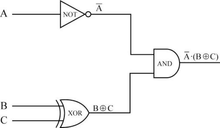
Behavior of the circuit:
- From the circuit diagram:
- First, the input A is passed to NOT gate to perform the inverse of A and produces the output as
- Next, the inputs B and C are passed into XOR gate to perform the XOR operation of the B and C to produce the output as
- Note: XOR operation - when both the inputs are the same, then the output of XOR gate is 0. Otherwise, the output of XOR gate is 1.
- Finally, the output of NOT gate and output of XOR gate is passed as the input of AND gate.
- That is, “
- That is, “
- First, the input A is passed to NOT gate to perform the inverse of A and produces the output as
Truth table:
Step 1:
- The inputs are A, B, and C for the above circuit diagram:
| A | B | C | |||
| 0 | 0 | 0 | |||
| 0 | 0 | 1 | |||
| 0 | 1 | 0 | |||
| 0 | 1 | 1 | |||
| 1 | 0 | 0 | |||
| 1 | 0 | 1 | |||
| 1 | 1 | 0 | |||
| 1 | 1 | 1 |
Step 2:
- When the inputs are A as 0, B as 0, and C as 0:
| A | B | C | |||
| 0 | 0 | 0 | 1 | 0 | 0 |
| 0 | 0 | 1 | |||
| 0 | 1 | 0 | |||
| 0 | 1 | 1 | |||
| 1 | 0 | 0 | |||
| 1 | 0 | 1 | |||
| 1 | 1 | 0 | |||
| 1 | 1 | 1 |
- First, the input A as 0 is passed to NOT gate to perform the inverse of the A and produces the output as
- Next, the inputs B as 0 and C as 0 are passed in the XOR gate to perform the XOR operation of 0 and 0, to produce the output as
- Note: XOR operation: when both the inputs are the same, the output of XOR gate is 0. Otherwise, the output of XOR gate is 1.
- Finally, the output of NOT gate and output of XOR gate are passed as the input of AND gate.
- That is, “1” and “0” are passed as input to AND gate and produces the output
- That is, “1” and “0” are passed as input to AND gate and produces the output
Step 3:
- When the inputs are A as 0, B as 0, and C as 1:
| A | B | C | |||
| 0 | 0 | 0 | 1 | 0 | 0 |
| 0 | 0 | 1 | 1 | 1 | 1 |
| 0 | 1 | 0 | |||
| 0 | 1 | 1 | |||
| 1 | 0 | 0 | |||
| 1 | 0 | 1 | |||
| 1 | 1 | 0 | |||
| 1 | 1 | 1 |
- First, the input A as 0 is passed to NOT gate to perform the inverse of the A and produces the output as
- Next, the inputs B as 0 and C as 1 are passed in the XOR gate to perform the XOR operation of 0 and 1, to produce the output as
- Note: XOR operation - when both the inputs are same, the output of XOR gate is 0. Otherwise, output of XOR gate will be 1.
- Finally, the output of NOT gate and output of XOR gate are passed as the input of AND gate.
- That is, “1” and “1” are passed as input to AND gate and produces the output
- That is, “1” and “1” are passed as input to AND gate and produces the output
Step 4:
- When the inputs are A as 0, B as 1, and C as 0:
| A | B | C | |||
| 0 | 0 | 0 | 1 | 0 | 0 |
| 0 | 0 | 1 | 1 | 1 | 1 |
| 0 | 1 | 0 | 1 | 1 | 1 |
| 0 | 1 | 1 | |||
| 1 | 0 | 0 | |||
| 1 | 0 | 1 | |||
| 1 | 1 | 0 | |||
| 1 | 1 | 1 |
- First, the input A as 0 is passed to NOT gate to perform the inverse of A and produces the output as
- Next, the inputs B as 1 and C as 0 are passed in the XOR gate to perform the XOR operation of the 1 and 0, to produce the output as
- Note: XOR operation - when both the inputs are same, the output of XOR gate is 0. Otherwise, the output of XOR gate is 1.
- Finally, the output of NOT gate and output of XOR gate are passed as the input of AND gate.
- That is, “1” and “1” are passed as input for AND gate and produces the output
- That is, “1” and “1” are passed as input for AND gate and produces the output
Step 5:
- When the inputs are A as 0, B as 1, and C as 1:
| A | B | C | |||
| 0 | 0 | 0 | 1 | 0 | 0 |
| 0 | 0 | 1 | 1 | 1 | 1 |
| 0 | 1 | 0 | 1 | 1 | 1 |
| 0 | 1 | 1 | 1 | 0 | 0 |
| 1 | 0 | 0 | |||
| 1 | 0 | 1 | |||
| 1 | 1 | 0 | |||
| 1 | 1 | 1 |
- First, the input A as 0 is passed to NOT gate to perform the inverse of the A and produces the output as
- Next, the inputs B as 1 and C as 1 are passed in the XOR gate to perform the XOR operation of the 1 and 1, to produce the output as
- Note: XOR operation - when both the inputs are same, the output of XOR gate is 0. Otherwise, the output of XOR gate is 1.
- Finally, the output of NOT gate and output of XOR gate are passed as the input of AND gate.
- That is, “1” and “0” are passed as input for AND gate and produces the output
- That is, “1” and “0” are passed as input for AND gate and produces the output
Step 6:
- When the inputs are A as 1, B as 0, and C as 0:
| A | B | C | |||
| 0 | 0 | 0 | 1 | 0 | 0 |
| 0 | 0 | 1 | 1 | 1 | 1 |
| 0 | 1 | 0 | 1 | 1 | 1 |
| 0 | 1 | 1 | 1 | 0 | 0 |
| 1 | 0 | 0 | 0 | 0 | 0 |
| 1 | 0 | 1 | |||
| 1 | 1 | 0 | |||
| 1 | 1 | 1 |
- First, the input A as 1 is passed to NOT gate to perform the inverse of the A and produces the output as
- Next, the inputs B as 0 and C as 0 are passed in the XOR gate to perform the XOR operation of the 0 and 0, to produce the output as
- Note: XOR operation - when both the inputs are same, the output of XOR gate is 0. Otherwise, the output of XOR gate is 1.
- Finally, the output of NOT gate and output of XOR gate are passed as the input of AND gate.
- That is, “0” and “0” are passed as input for AND gate and produces the output
- That is, “0” and “0” are passed as input for AND gate and produces the output
Step 7:
- When the inputs are A as 1, B as 0, and C as 1:
| A | B | C | |||
| 0 | 0 | 0 | 1 | 0 | 0 |
| 0 | 0 | 1 | 1 | 1 | 1 |
| 0 | 1 | 0 | 1 | 1 | 1 |
| 0 | 1 | 1 | 1 | 0 | 0 |
| 1 | 0 | 0 | 0 | 0 | 0 |
| 1 | 0 | 1 | 0 | 1 | 0 |
| 1 | 1 | 0 | |||
| 1 | 1 | 1 |
- First, the input A as 1 is passed to NOT gate to perform the inverse of the A and produces the output as
- Next, the inputs B as 0 and C as 1 are passed in the XOR gate to perform the XOR operation of the 0 and 0, to produce the output as
- Note: XOR operation - when both the inputs are same, the output of XOR gate is 0. Otherwise, the output of XOR gate is 1.
- Finally, the output of NOT gate and output of XOR gate are passed as the input of AND gate.
- That is, “0” and “1” are passed as input for AND gate and produces the output
- That is, “0” and “1” are passed as input for AND gate and produces the output
Step 8:
- When the inputs are A as 1, B as 1, and C as 0:
| A | B | C | |||
| 0 | 0 | 0 | 1 | 0 | 0 |
| 0 | 0 | 1 | 1 | 1 | 1 |
| 0 | 1 | 0 | 1 | 1 | 1 |
| 0 | 1 | 1 | 1 | 0 | 0 |
| 1 | 0 | 0 | 0 | 0 | 0 |
| 1 | 0 | 1 | 0 | 1 | 0 |
| 1 | 1 | 0 | 0 | 1 | 0 |
| 1 | 1 | 1 |
- First, the input A as 1 is passed to NOT gate to perform the inverse of the A and produces the output as
- Next, the inputs B as 1 and C as 0 are passed in the XOR gate to perform the XOR operation of the 0 and 0, to produce the output as
- Note: XOR operation - when both the inputs are same, the output of XOR gate is 0. Otherwise, the output of XOR gate is 1.
- Finally, the output of NOT gate and output of XOR gate are passed as the input of AND gate.
- That is, “0” and “1” are passed as input to AND gate and produces the output
- That is, “0” and “1” are passed as input to AND gate and produces the output
Step 9:
- When the inputs are A as 1, B as 1, and C as 1:
| A | B | C | |||
| 0 | 0 | 0 | 1 | 0 | 0 |
| 0 | 0 | 1 | 1 | 1 | 1 |
| 0 | 1 | 0 | 1 | 1 | 1 |
| 0 | 1 | 1 | 1 | 0 | 0 |
| 1 | 0 | 0 | 0 | 0 | 0 |
| 1 | 0 | 1 | 0 | 1 | 0 |
| 1 | 1 | 0 | 0 | 1 | 0 |
| 1 | 1 | 1 | 0 | 0 | 0 |
- First, the input A as 1 is passed to NOT gate to perform the inverse of the A and produces the output as
- Next, the inputs B as 1 and C as 1 are passed in the XOR gate to perform the XOR operation of the 0 and 0, to produce the output as
- Note: XOR operation - when both the inputs are same, the output of XOR gate is 0. Otherwise, the output of XOR gate is 1.
- Finally, the output of NOT gate and output of XOR gate are passed as the input of AND gate.
- That is, “0” and “0” are passed as input for AND gate and produces the output
- That is, “0” and “0” are passed as input for AND gate and produces the output
Therefore, Truth table for the given circuit is:
| A | B | C | |||
| 0 | 0 | 0 | 1 | 0 | 0 |
| 0 | 0 | 1 | 1 | 1 | 1 |
| 0 | 1 | 0 | 1 | 1 | 1 |
| 0 | 1 | 1 | 1 | 0 | 0 |
| 1 | 0 | 0 | 0 | 0 | 0 |
| 1 | 0 | 1 | 0 | 1 | 0 |
| 1 | 1 | 0 | 0 | 1 | 0 |
| 1 | 1 | 1 | 0 | 0 | 0 |
Want to see more full solutions like this?
Subscribe now to access step-by-step solutions to millions of textbook problems written by subject matter experts!
Students have asked these similar questions
1. What is the difference between a relative cell reference and an absolute cell reference and give an example of when you would use each.
What is the goal of using a chart in excel, and how is a chart useful and what is the goal of using sparklines in excel, and how are sparklines useful?
Prove for each pair of expression f(n) and g(n) whether f(n) is big O, little o Ω,ω or Θ of g(n). Use limits to find these. For each case it is possible that more than one of these conditions is satisfied:1. f(n) =log(n2^n), g(n) = log(sqrt(n)2^(n^2))2. f(n) =nsqrt(n) +log(n^n), g(n) =n + sqrt(n)logn
Chapter 4 Solutions
Computer Science Illuminated
Ch. 4 - Prob. 1ECh. 4 - Prob. 2ECh. 4 - Prob. 3ECh. 4 - Prob. 4ECh. 4 - Prob. 5ECh. 4 - Prob. 6ECh. 4 - Prob. 7ECh. 4 - Prob. 8ECh. 4 - Prob. 9ECh. 4 - Prob. 10E
Ch. 4 - Prob. 11ECh. 4 - Prob. 12ECh. 4 - Prob. 13ECh. 4 - Prob. 14ECh. 4 - Prob. 15ECh. 4 - Prob. 16ECh. 4 - Prob. 17ECh. 4 - Prob. 18ECh. 4 - Prob. 19ECh. 4 - Prob. 20ECh. 4 - Prob. 21ECh. 4 - Prob. 22ECh. 4 - Prob. 23ECh. 4 - Prob. 24ECh. 4 - Prob. 25ECh. 4 - Prob. 26ECh. 4 - Prob. 27ECh. 4 - Prob. 28ECh. 4 - Prob. 29ECh. 4 - Prob. 30ECh. 4 - Prob. 31ECh. 4 - Prob. 32ECh. 4 - Prob. 33ECh. 4 - Prob. 34ECh. 4 - Prob. 35ECh. 4 - Prob. 36ECh. 4 - Prob. 37ECh. 4 - Prob. 38ECh. 4 - Prob. 39ECh. 4 - Prob. 40ECh. 4 - Prob. 41ECh. 4 - Prob. 42ECh. 4 - Prob. 43ECh. 4 - Prob. 44ECh. 4 - Prob. 45ECh. 4 - Prob. 46ECh. 4 - Prob. 47ECh. 4 - Prob. 48ECh. 4 - Prob. 49ECh. 4 - Prob. 50ECh. 4 - Prob. 51ECh. 4 - Prob. 52ECh. 4 - Prob. 53ECh. 4 - Prob. 54ECh. 4 - Prob. 55ECh. 4 - Prob. 56ECh. 4 - Prob. 57ECh. 4 - Prob. 58ECh. 4 - Prob. 59ECh. 4 - Prob. 60ECh. 4 - Prob. 61ECh. 4 - Prob. 62ECh. 4 - Prob. 63ECh. 4 - Prob. 64ECh. 4 - Prob. 65ECh. 4 - Prob. 66ECh. 4 - Prob. 67ECh. 4 - Prob. 68ECh. 4 - Prob. 69ECh. 4 - Prob. 70ECh. 4 - Prob. 71ECh. 4 - Prob. 72ECh. 4 - Prob. 73ECh. 4 - Prob. 1TQCh. 4 - Prob. 2TQCh. 4 - Prob. 3TQCh. 4 - Prob. 4TQ
Knowledge Booster


Learn more about
Need a deep-dive on the concept behind this application? Look no further. Learn more about this topic, computer-science and related others by exploring similar questions and additional content below.Similar questions
- Need this expression solved for mu. This can be done using a symbolic toolbox, however it needs to end up being mu = function (theta, m, L, g). If using MATLAB or something similar, run the code to make sure it works.arrow_forwardA business case scenario and asked to formulate an appropriate software design solution. Theyshould complete the case and upload the solution. will be required to read the case,identify and document the key issues, problems, and opportunities presented, and then design,and develop an appropriate integrated design solution to the problem. mustdemonstrate good spreadsheet, database, analytical, and word-processing skills whendeveloping solutions. Additionally, must be creative and demonstrate synthesising andapplying Database Management and Data Analytics Principles learned in the course. They willalso need to research some aspects of the assessment. CASE BACKGROUNDMGMT SS STATS, an umbrella body that facilitates and serves various Social SecurityOrganizations/Departments within the Caribbean territories, stoodpoised to meet the needs of its stakeholders by launching an onlinedatabase at www.SSDCI.gov. The database will provide membersand the public access to the complete set of…arrow_forwardA business case scenario and asked to formulate an appropriate software design solution. Theyshould complete the case and upload the solution. will be required to read the case,identify and document the key issues, problems, and opportunities presented, and then design,and develop an appropriate integrated design solution to the problem. mustdemonstrate good spreadsheet, database, analytical, and word-processing skills whendeveloping solutions. Additionally, must be creative and demonstrate synthesising andapplying Database Management and Data Analytics Principles learned in the course. They willalso need to research some aspects of the assessment. CASE BACKGROUNDMGMT SS STATS, an umbrella body that facilitates and serves various Social SecurityOrganizations/Departments within the Caribbean territories, stoodpoised to meet the needs of its stakeholders by launching an onlinedatabase at www.SSDCI.gov. The database will provide membersand the public access to the complete set of…arrow_forward
- Using MATLAB symbolic toolbox, given these 3 equations, how would you solve for mu = function(theta), making sure that there are no mu's on the right hand side, making sure theta-dot-dot, theta-dot-squared- and N aren't in the final answer either.arrow_forwardAfter playing our giving implementation, your task is to implement Dinning Philosophers with semaphore in C, by including and Your implementation will require creating five philosophers, each identified by a number 0.4. Each philosopher will run as a separate thread. Create threads using Pthreads as discussed in the Lecture slides on Chapter 4 and Practice Lab on Threads. Your solution needs to accomplish the following: Implement in C (15 points) 1. dp1.c - You are to provide your solution to this assignment as a single C program named 'dp1.c using semaphore. Explain in you code (as comments) that the dead lock will happen or not. If there is a possible deadlock, you can simply solve the deadlock by pick the fork in order like the first solution in our slides. Solve Deadlock by Footman (15 points) 1. Here is a new solution to overcome the deadlock. The Dining Philosophers decide to hire a footman whose task to allow only four philosophers to sit on the table. When entering and…arrow_forward8.4 Self-Bias Configuration 20. Determine Zi. Zo. and A,, for the network of Fig. 8.73 if gf, = 3000 μS and gos = 50 μs. 21. Determine Z, Zo, and A, for the network of Fig. 8.73 if the 20-uF capacitor is removed and the parameters of the network are the same as in Problem 20. Compare results with those of Problem 20. +12 V 3.3 ΚΩ HE C₂ Vo Z Zo C₁ 10 ΜΩ Z₁ 1.1 ΚΩ Cs 20 µF FIG. 8.73 Problems 20, 21, 22, and 59.arrow_forward
- 21. Determine Zi, Zo, and A, for the network of Fig. 8.73 if the 20-μF capacitor is removed and the parameters of the network are the same as in Problem 20. Compare results with those of Problem 20. +12 V 3.3 ΚΩ +6 C₂ C₁ Z₁ 10 ΜΩ 1.1 ΚΩ Cs 20 μF FIG. 8.73 Zoarrow_forwardNinth Edition Determine Zi, Zo and Av 20 V Zi + 1 ΜΩ 2 ΚΩ HH Z IDSS= 6MA Vp=-6V Yos = 40μS 20 and 47arrow_forwardWhat is the worst case time complexity of the following algorithm for i = 1 to x do for j = 2^((i-1)x) to 2^(in) do print(i,j)arrow_forward
- Prove for each pair of expression f(n) and g(n) whether f(n) is big O, little o Ω,ω or Θ of g(n). For each case it is possible that more than one of these conditions is satisfied:1. f(n) =log(n2^n), g(n) = log(sqrt(n)2^(n^2))2. f(n) =nsqrt(n) +log(n^n), g(n) =n + sqrt(n)lognarrow_forwardI need to make a parallel version of this sequential codearrow_forwardI need to make a parallel version of this sequential code.arrow_forward
arrow_back_ios
SEE MORE QUESTIONS
arrow_forward_ios
Recommended textbooks for you
 Database System ConceptsComputer ScienceISBN:9780078022159Author:Abraham Silberschatz Professor, Henry F. Korth, S. SudarshanPublisher:McGraw-Hill Education
 Starting Out with Python (4th Edition)Computer ScienceISBN:9780134444321Author:Tony GaddisPublisher:PEARSON
 Digital Fundamentals (11th Edition)Computer ScienceISBN:9780132737968Author:Thomas L. FloydPublisher:PEARSON
 C How to Program (8th Edition)Computer ScienceISBN:9780133976892Author:Paul J. Deitel, Harvey DeitelPublisher:PEARSON
 Database Systems: Design, Implementation, & Manag...Computer ScienceISBN:9781337627900Author:Carlos Coronel, Steven MorrisPublisher:Cengage Learning
 Programmable Logic ControllersComputer ScienceISBN:9780073373843Author:Frank D. PetruzellaPublisher:McGraw-Hill Education
Database System Concepts
Computer Science
ISBN:9780078022159
Author:Abraham Silberschatz Professor, Henry F. Korth, S. Sudarshan
Publisher:McGraw-Hill Education
Starting Out with Python (4th Edition)
Computer Science
ISBN:9780134444321
Author:Tony Gaddis
Publisher:PEARSON
Digital Fundamentals (11th Edition)
Computer Science
ISBN:9780132737968
Author:Thomas L. Floyd
Publisher:PEARSON
C How to Program (8th Edition)
Computer Science
ISBN:9780133976892
Author:Paul J. Deitel, Harvey Deitel
Publisher:PEARSON
Database Systems: Design, Implementation, & Manag...
Computer Science
ISBN:9781337627900
Author:Carlos Coronel, Steven Morris
Publisher:Cengage Learning
Programmable Logic Controllers
Computer Science
ISBN:9780073373843
Author:Frank D. Petruzella
Publisher:McGraw-Hill Education
Boolean Algebra - Digital Logic and Logic Families - Industrial Electronics; Author: Ekeeda;https://www.youtube.com/watch?v=u7XnJos-_Hs;License: Standard YouTube License, CC-BY
Boolean Algebra 1 – The Laws of Boolean Algebra; Author: Computer Science;https://www.youtube.com/watch?v=EPJf4owqwdA;License: Standard Youtube License