International Edition---engineering Mechanics: Statics 4th Edition
4th Edition
ISBN: 9781305856240
Author: Pytel
Publisher: Cengage
expand_more
expand_more
format_list_bulleted
Videos
Textbook Question
Chapter 4, Problem 4.8P
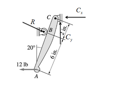
The figure models the handle of the water cock described in Prob. 4.9. Draw the FBD of the handle, neglecting its weight. Count the unknowns.
Expert Solution & Answer
Want to see the full answer?
Check out a sample textbook solution
Students have asked these similar questions
The fallowing question is from a reeds book on applied heat i am studying. Although the answer is provided, im struggling to understand the whole answer and the formulas and the steps theyre using. Also where some ov the values such as Hg and Hf come from in part i for example. Please explain step per step in detail thanks
In an NH, refrigerator, the ammonia leaves the evaporatorand enters the cornpressor as dry saturated vapour at 2.68 bar,it leaves the compressor and enters the condenser at 8.57 bar with50" of superheat. it is condensed at constant pressure and leavesthe condenser as saturated liquid. If the rate of flow of the refrigerantthrough the circuit is 0.45 kglmin calculate
(i) the compressorpower,
(ii) the heat rejected to the condenser cooling water in kJ/s,an (iii) the refrigerating effect in kJ/s.
From tables page 12, NH,:2.68 bar, hg= 1430.58.57 bar, hf = 275.1 h supht 50" = 1597.2Mass flow of refrigerant--- - - 0.0075 kgls 60Enthalpy gain per kg of refrigerant in…
state the formulas for calculating work done by gas
Exercises
Find the solution of the following Differential Equations
1) y" + y = 3x²
3)
"+2y+3y=27x
5) y"+y=6sin(x)
7) y"+4y+4y = 18 cosh(x)
9) (4)-5y"+4y = 10 cos(x)
11) y"+y=x²+x
13) y"-2y+y=e*
15) y+2y"-y'-2y=1-4x³
2) y"+2y' + y = x²
4) "+y=-30 sin(4x)
6) y"+4y+3y=sin(x)+2 cos(x)
8) y"-2y+2y= 2e* cos(x)
10) y+y-2y=3e*
12) y"-y=e*
14) y"+y+y=x+4x³ +12x²
16) y"-2y+2y=2e* cos(x)
Chapter 4 Solutions
International Edition---engineering Mechanics: Statics 4th Edition
Ch. 4 - Each of the bodies shown is homogeneous and has a...Ch. 4 - Each of the bodies shown is homogeneous and has a...Ch. 4 - Each of the bodies shown is homogeneous and has a...Ch. 4 - The homogeneous bar weighs 12 lb. It is resting on...Ch. 4 - The homogeneous beam AB weighs 400 lb. For each...Ch. 4 - The homogeneous triangular plate has a mass of 12...Ch. 4 - The bracket of negligible weight is supported by a...Ch. 4 - The figure models the handle of the water cock...Ch. 4 - The high-pressure water cock is rigidly attached...Ch. 4 - Draw the FBD of the entire frame, assuming that...
Ch. 4 - The figure is a model for member CDE of the frame...Ch. 4 - The homogeneous cylinder of weight Wrests in a...Ch. 4 - Calculate the force P that is required to hold the...Ch. 4 - The 60-lb homogeneous disk is suspended from a...Ch. 4 - The 180-kg uniform boom ABC, supported by a...Ch. 4 - The table lamp consists of two uniform arms, each...Ch. 4 - At what angle will the lamp in Prob. 4.16 be in...Ch. 4 - The bent beam ABC is supported by a pin at B and a...Ch. 4 - Compute all reactions at the base A of the traffic...Ch. 4 - The man is holding up the 35-kg ladder ABC by...Ch. 4 - The 1200-lb homogeneous block is placed on rollers...Ch. 4 - The uniform plank ABC weighs 400 N. It is...Ch. 4 - The center of gravity of the 850-N man is at G. If...Ch. 4 - The homogeneous 340-lb sign is suspended from...Ch. 4 - When the truck is empty, it weighs 6000 lb and its...Ch. 4 - The homogeneous bar AB weighs 25 lb. Determine the...Ch. 4 - Determine the smallest horizontal force P that...Ch. 4 - The homogeneous beam AB weighing 800 lb carries...Ch. 4 - The homogeneous 40-kg bar ABC is held in position...Ch. 4 - The horizontal force P is applied to the handle of...Ch. 4 - The homogeneous plate of weight W is suspended...Ch. 4 - Neglecting the mass of the beam, compute the...Ch. 4 - The 1200-kg car is being lowered slowly onto the...Ch. 4 - The crate weighing 400 lb is supported by three...Ch. 4 - Find the smallest value of P for which the crate...Ch. 4 - Determine the rope tension T for which the pulley...Ch. 4 - The 40-kg homogeneous disk is resting on an...Ch. 4 - The 40-kghomogeneous disk is placed on a...Ch. 4 - The mass of the uniform bar AB is 80 kg. Calculate...Ch. 4 - The mechanism shown is a modified Geneva drive-a...Ch. 4 - The center of gravity of the 3000-lb car is at G....Ch. 4 - The 30-lb block is held in place on the smooth...Ch. 4 - The vertical post is supported by two cables (the...Ch. 4 - The uniform ladder of weight W is raised slowly by...Ch. 4 - The uniform, 30-lb ladder is raised slowly by...Ch. 4 - The 90-kg man, whose center of gravity is at G, is...Ch. 4 - The bar ABC is constrained by the pin support A...Ch. 4 - The tensioning mechanism of a magnetic tape drive...Ch. 4 - The homogeneous 300-kg cylinder is pulled over the...Ch. 4 - Compute the magnitudes of the reactions at pin A...Ch. 4 - Each of the sandbags piled on the 380-lb uniform...Ch. 4 - The 18-ft pole is supported by a pin at A and a...Ch. 4 - The supporting structure of the billboard is...Ch. 4 - The self-regulating floodgate ABC, pinned at B, is...Ch. 4 - The cantilever beam is built into a wall at O....Ch. 4 - Determine the force F required to keep the 200-kg...Ch. 4 - The uniform rod AB of weight W is supported by the...Ch. 4 - A machine operator produces the tension Tin the...Ch. 4 - The dump truck consists of a chassis and a tray,...Ch. 4 - The centers of gravity of the 50-kg lift truck and...Ch. 4 - (a) draw the free-body diagrams for the entire...Ch. 4 - (a) draw the free-body diagrams for the entire...Ch. 4 - For Probs. 4.61–4.68, (a) draw the free-body...Ch. 4 - (a) draw the free-body diagrams for the entire...Ch. 4 - (a) draw the free-body diagrams for the entire...Ch. 4 - (a) draw the free-body diagrams for the entire...Ch. 4 - (a) draw the free-body diagrams for the entire...Ch. 4 - (a) draw the free-body diagrams for the entire...Ch. 4 - The two uniform cylinders, each of weight W, are...Ch. 4 - Draw the FBDs for the following: (a) bar ABC with...Ch. 4 - Draw the FBDs for the beam ABC and the segments AB...Ch. 4 - Draw the FBDs for the entire structure and the...Ch. 4 - The beam consists of the bars AB and BC connected...Ch. 4 - For the frame shown, determine the magnitude of...Ch. 4 - Determine the magnitudes of the pin reactions at A...Ch. 4 - The bars AB and AC are joined by a pin at A and a...Ch. 4 - Neglecting the weights of the members, determine...Ch. 4 - Calculate the magnitudes of the pin reactions at A...Ch. 4 - Determine the magnitude of the pin reaction at A...Ch. 4 - Neglecting friction and the weights of the...Ch. 4 - When activated by the force P, the gripper on a...Ch. 4 - Determine the axle loads (normal forces at A, B,...Ch. 4 - Determine the force P that would produce a tensile...Ch. 4 - The pulley-cable system supports the 150-lb...Ch. 4 - Determine the contact force between the smooth...Ch. 4 - Compute the tension in the cable and the contact...Ch. 4 - Determine the magnitude of the pin reaction at B....Ch. 4 - Determine the tension in the cable at B, given...Ch. 4 - Compute the magnitude of the pin reaction at B....Ch. 4 - Neglecting the weight of the frame, find the...Ch. 4 - Determine the clamping force at A due to the 15-lb...Ch. 4 - Compute the tension in the cable BD when the...Ch. 4 - Calculate the reactions at the built-in support at...Ch. 4 - Determine the magnitudes of the roller reactions...Ch. 4 - The linkage of the braking system consists of the...Ch. 4 - The window washers A and B support themselves and...Ch. 4 - The figure shows a wire cutter. Determine the...Ch. 4 - Find the tension T in the cable when the 180-N...Ch. 4 - The 400-kg drum is held by tongs of negligible...Ch. 4 - Compute the magnitudes of all forces acting on...Ch. 4 - Calculate all forces acting on member CDB.Ch. 4 - The automatic drilling robot must sustain a thrust...Ch. 4 - Determine the clamping (vertical) force applied by...Ch. 4 - Determine the axial force in member BC of the...Ch. 4 - Neglecting friction, determine the relationship...Ch. 4 - Find the magnitudes of the pin reactions at A and...Ch. 4 - The load in the bucket of a skid steer loader is...Ch. 4 - Determine the magnitude of the roller reaction at...Ch. 4 - The tool shown is used to crimp terminals onto...Ch. 4 - The 12-lb force is applied to the handle of the...Ch. 4 - The blade of the bulldozer is rigidly attached to...Ch. 4 - Find the magnitudes of the pin reactions at A, C,...Ch. 4 - The pins at the end of the retaining-ring spreader...Ch. 4 - Determine the magnitudes of the support reactions...Ch. 4 - Find the magnitude of the pin reaction at C....Ch. 4 - For the pliers shown, determine the relationship...Ch. 4 - The device shown is an overload prevention...Ch. 4 - The figure is a schematic of a wire cutter....Ch. 4 - The hinge shown is the type used on the doors of...Ch. 4 - Determine the force in the hydraulic cylinder EF...Ch. 4 - Determine the horizontal force P that would keep...Ch. 4 - Determine the magnitudes of the forces acting on...Ch. 4 - Determine the angle at which the bar AB is in...Ch. 4 - The automobile, with center of gravity at G, is...Ch. 4 - The figure shows a three-pin arch. Determine the...Ch. 4 - The center of gravity of the nonhomogeneous bar AB...Ch. 4 - When suspended from two cables, the rocket assumes...Ch. 4 - The pump oiler is operated by pressing on the...Ch. 4 - The uniform 240-lb bar AB is held in the position...Ch. 4 - Find the force P required to (a) push; and (b)...Ch. 4 - Using the method of joints, calculate the force in...Ch. 4 - Using the method of joints, calculate the force in...Ch. 4 - Using the method of joints, calculate the force in...Ch. 4 - Using the method of joints, calculate the force in...Ch. 4 - Using the method of joints, calculate the force in...Ch. 4 - Using the method of joints, calculate the force in...Ch. 4 - Using the method of joints, calculate the force in...Ch. 4 - Using the method of joints, calculate the force in...Ch. 4 - Using the method of joints, calculate the force in...Ch. 4 - Using the method of joints, calculate the force in...Ch. 4 - Identify all the zero-force members in the four...Ch. 4 - The walkway ABC of the footbridge is stiffened by...Ch. 4 - Find the force in member EF.Ch. 4 - Determine the forces in members AE, BE, and ED.Ch. 4 - Determine the reaction at E and the force in each...Ch. 4 - Determine the force in member AD of the truss.Ch. 4 - Determine the force in member BE of the truss.Ch. 4 - Show that all diagonal members of the truss carry...Ch. 4 - Determine the forces in members FG and AB in terms...Ch. 4 - Determine the forces in members BC, BG, and FG.Ch. 4 - Determine the forces in members EF, BF, and BC.Ch. 4 - Compute the forces in members EF, NE and NO.Ch. 4 - Repeat Prob. 4.152 assuming that the 400-kN force...Ch. 4 - Determine the forces in members BG, CI, and CD.Ch. 4 - Assuming that P=48000lb and that it may be applied...Ch. 4 - Calculate the forces in members BC, CF, and FG.Ch. 4 - Find the forces in members CD, DH, and HI.Ch. 4 - Determine the forces in members CD and DF.Ch. 4 - Compute the forces in members CD and JK, given...Ch. 4 - If PCD=6000lb and PGD=1000lb (both compression),...Ch. 4 - Determine the forces in members EF, BF, and BC.Ch. 4 - Determine the forces in members AC, AD, and DE.Ch. 4 - Determine the forces in members GI, PH, and GH....Ch. 4 - Determine the forces in members CD, IJ, and NJ of...Ch. 4 - Calculate the forces in members AB and DE.Ch. 4 - (a) Find the forces in members CE, CF, and DF. (b)...Ch. 4 - Determine the forces in members BC and BE and the...Ch. 4 - A couple acting on the winch at G slowly raises...Ch. 4 - The uniform, 20-kg bar is placed between two...Ch. 4 - The 320-lb homogeneous spool is placed on the...Ch. 4 - Determine the magnitude of the pin reaction at A,...Ch. 4 - Determine the couple C that will hold the bar AB...Ch. 4 - The 800-lb force is applied to the pin at E....Ch. 4 - The weight W=6kN hangs from the cable which passes...Ch. 4 - The 2000-lb and 6000-lb forces are applied to the...Ch. 4 - The two couples act at the midpoints of bars AB...Ch. 4 - Determine the forces in members AC and AD of the...Ch. 4 - Determine the angle for which the uniform bar of...Ch. 4 - Determine the magnitude of the force exerted by...Ch. 4 - Calculate the forces in members (a) DE; (b) BE;...Ch. 4 - Determine the ratio P/Q for which the parallel...Ch. 4 - The 30-lb block C rests on the uniform 14-lb bar...Ch. 4 - The 30-lb homogeneous bar AB supports the 60-lb...Ch. 4 - Determine the forces in members (a) EF; and (b)...Ch. 4 - Find the magnitude of the pin reaction at B caused...Ch. 4 - The breaking strength of the cable FG that...Ch. 4 - Determine the forces in members GH, BH, and BC of...Ch. 4 - The 80-N force is applied to the handle of the...Ch. 4 - The tongs shown are designed for lifting blocks of...
Knowledge Booster


Learn more about
Need a deep-dive on the concept behind this application? Look no further. Learn more about this topic, mechanical-engineering and related others by exploring similar questions and additional content below.Similar questions
- The state of stress at a point is σ = -4.00 kpsi, σy = 16.00 kpsi, σ = -14.00 kpsi, Try = 11.00 kpsi, Tyz = 8.000 kpsi, and T = -14.00 kpsi. Determine the principal stresses. The principal normal stress σ₁ is determined to be [ The principal normal stress σ2 is determined to be [ The principal normal stress σ3 is determined to be kpsi. kpsi. The principal shear stress 71/2 is determined to be [ The principal shear stress 7½ is determined to be [ The principal shear stress T₁/, is determined to be [ kpsi. kpsi. kpsi. kpsi.arrow_forwardRepeat Problem 28, except using a shaft that is rotatingand transmitting a torque of 150 N * m from the left bearing to the middle of the shaft. Also, there is a profile keyseat at the middle under the load. (I want to understand this problem)arrow_forwardProb 2. The material distorts into the dashed position shown. Determine the average normal strains &x, Ey and the shear strain Yxy at A, and the average normal strain along line BE. 50 mm B 200 mm 15 mm 30 mm D ΕΙ 50 mm x A 150 mm Farrow_forward
- Prob 3. The triangular plate is fixed at its base, and its apex A is given a horizontal displacement of 5 mm. Determine the shear strain, Yxy, at A. Prob 4. The triangular plate is fixed at its base, and its apex A is given a horizontal displacement of 5 mm. Determine the average normal strain & along the x axis. Prob 5. The triangular plate is fixed at its base, and its apex A is given a horizontal displacement of 5 mm. Determine the average normal strain &x along the x' axis. x' 45° 800 mm 45° 45% 800 mm 5 mmarrow_forwardAn airplane lands on the straight runaway, originally travelling at 110 ft/s when s = 0. If it is subjected to the decelerations shown, determine the time t' needed to stop the plane and construct the s -t graph for the motion. draw a graph and show all work step by steparrow_forwarddny dn-1y dn-1u dn-24 +a1 + + Any = bi +b₂- + +bnu. dtn dtn-1 dtn-1 dtn-2 a) Let be a root of the characteristic equation 1 sn+a1sn- + +an = : 0. Show that if u(t) = 0, the differential equation has the solution y(t) = e\t. b) Let к be a zero of the polynomial b(s) = b₁s-1+b2sn−2+ Show that if the input is u(t) equation that is identically zero. = .. +bn. ekt, then there is a solution to the differentialarrow_forward
- B 60 ft WAB AB 30% : The crane's telescopic boom rotates with the angular velocity w = 0.06 rad/s and angular acceleration a = 0.07 rad/s². At the same instant, the boom is extending with a constant speed of 0.8 ft/s, measured relative to the boom. Determine the magnitude of the acceleration of point B at this instant.arrow_forwardThe motion of peg P is constrained by the lemniscate curved slot in OB and by the slotted arm OA. (Figure 1) If OA rotates counterclockwise with a constant angular velocity of 0 = 3 rad/s, determine the magnitude of the velocity of peg P at 0 = 30°. Express your answer to three significant figures and include the appropriate units. Determine the magnitude of the acceleration of peg P at 0 = 30°. Express your answer to three significant figures and include the appropriate units. 0 (4 cos 2 0)m² B Aarrow_forward5: The structure shown was designed to support a30-kN load. It consists of a boom AB with a 30 x 50-mmrectangular cross section and a rod BC with a 20-mm-diametercircular cross section. The boom and the rod are connected bya pin at B and are supported by pins and brackets at A and C,respectively.1. Calculate the normal stress in boom AB and rod BC,indicate if in tension or compression.2. Calculate the shear stress of pins at A, B and C.3. Calculate the bearing stresses at A in member AB,and in the bracket.arrow_forward
- 4: The boom AC is a 4-in. square steel tube with a wallthickness of 0.25 in. The boom is supported by the 0.5-in.-diameter pinat A, and the 0.375-in.-diameter cable BC. The working stresses are 25ksi for the cable, 18 ksi for the boom, and 13.6 ksi for shear in the pin.Neglect the weight of the boom.1. Calculate the maximum value of P (kips) based on boom compression and the maximum value of P (kips) based on tension in the cable.2. Calculate the maximum value of P (kips) based on shear in pin.arrow_forward3: A steel strut S serving as a brace for a boat hoist transmits a compressive force P = 54 kN to the deck of a pier as shown in Fig. STR-08. The strut has a hollow square cross section with a wall thickness t =12mm and the angle θ between the strut and the horizontal is 40°. A pin through the strut transmits the compressive force from the strut to two gusset plates G that are welded to the base plate B. Four anchor bolts fasten the base plate to the deck. The diameter of the pin is 20mm, the thickness of the gusset plates is 16mm, the thickness of the base plate is 8mm, and the diameter of the anchor bolts is 12mm. Disregard any friction between the base plate and the deck.1. Determine the shear stress in the pin, in MPa and the shear stress in the anchor bolts, in MPa.2. Determine the bearing stress in the strut holes, in MPa.arrow_forward1. In the figure, the beam, W410x67, with 9 mm web thicknesssubjects the girder, W530x109 with 12 mm web thickness to a shear load,P (kN). 2L – 90 mm × 90 mm × 6 mm with bolts frame the beam to thegirder.Given: S1 = S2 = S5 = 40 mm; S3 = 75 mm; S4 = 110 mmAllowable Stresses are as follows:Bolt shear stress, Fv = 125 MPaBolt bearing stress, Fp = 510 MPa1. Determine the allowable load, P (kN), based on the shearcapacity of the 4 – 25 mm diameter bolts (4 – d1) and calculate the allowable load, P (kN), based on bolt bearing stress on the web of the beam.2. If P = 450 kN, determine the minimum diameter (mm) of 4 – d1based on allowable bolt shear stress and bearing stress of thebeam web.arrow_forward
arrow_back_ios
SEE MORE QUESTIONS
arrow_forward_ios
Recommended textbooks for you
 International Edition---engineering Mechanics: St...Mechanical EngineeringISBN:9781305501607Author:Andrew Pytel And Jaan KiusalaasPublisher:CENGAGE L
International Edition---engineering Mechanics: St...
Mechanical Engineering
ISBN:9781305501607
Author:Andrew Pytel And Jaan Kiusalaas
Publisher:CENGAGE L
How to balance a see saw using moments example problem; Author: Engineer4Free;https://www.youtube.com/watch?v=d7tX37j-iHU;License: Standard Youtube License