The equation of motion of the pendulum.
Answer to Problem 4.69P
Explanation of Solution
Given:
A spring with stiffness k, and a damper with damping coefficient c, are attached to a pendulum with an input y(t)
Concept used:
For an objects’ planar motion which rotates only about an axis perpendicular to the plane, the equation of motion can be written down using Newton’s Second Law.
Equation of Motion:
Where
Let the angular displacement be
The angular velocity,
Hence, the equation of motion of this object can be rewritten by substituting,
To find the equation of motion, the required unknowns are
The rod inertia about the pivot is given as I.
Moments = Perpendicular Force
In this question the pivot is point O.
Total moments about O = Moments of spring element + Moments of damper with spring element.
Free body diagram of the system:
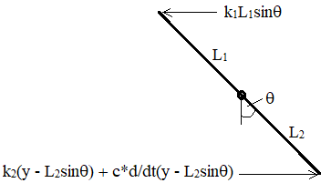
Moments of the spring element:
Using the Hooke’s Law, a linear force-deflection model can be written,
Where f = restoring force
x = compression or extension distance
k = Spring constant or stiffness
Here the extension distance,
Hence the moments due to spring element =
Moments of the Damper together with Spring element:
The linear model for the force applied by the damper is:
Where f = damping force
v = relative velocity
c = damping coefficient
The damper and spring element are connected parallelly, the forces of these elements can be added together to get the total force.
The distance of compression of the spring element is
Force,
The distance between the pivot, O and the force applied =
Hence Moments =
Taking anticlockwise to be positive as the input y(t) is taken positive in the anticlockwise direction.
Substitute the above expressions to the following equation,
Total moments about O = Moments of spring element + Moments of damper with spring element.
Total moments =
Derivation of Equation of Motion:
Substitute
Assuming
Substituting
Simplifying the equation further:
Conclusion:
The equation of motion of the pendulum is
Want to see more full solutions like this?
Chapter 4 Solutions
EBK SYSTEM DYNAMICS

- 2nd Law of Thermodynamics A 1.5-ft3 rigid tank contains saturated refrigerant-134 at 170 psia. Initially, 20 percent of the volume isoccupied by liquid and the rest by vapor. A valve at the top of the tank is now opened, and vapor is allowedto escape slowly from the tank. Heat is transferred to the refrigerant such that the pressure inside the tankremains constant. The valve is closed when the last drop of liquid in the tank is vaporized. Determine thetotal heat transfer for this process.arrow_forwardDraw the shear and bending-moment diagrams for the beam and loading shown, and determine the maximum normal stress due to bending. 4.8 kips/ft 32 kips B C D E I Hinge 8 ft. 2 ft 5 ft 5 ft W12 x 40arrow_forward2nd Law of Thermodynamics A rigid, insulated tank that is initially evacuated is connected through a valve to the supply line that carrieshelium at 300 kPa and 140◦C. Now the valve is opened, and helium is allowed to flow into the tank until thepressure reaches 300 kPa, at which point the valve is closed. Determine the flow work of the helium in thesupply line and the final temperature of the helium in the tank.arrow_forward
- Draw the shear and bending-moment diagrams for the beam and loading shown, and determine the maximum normal stress due to bending. 5 kips 10 kips B I W14 x 22 -5 ft -8 ft 5 ft-arrow_forward2nd Law of Thermodynamics Liquid water at 200 kPa and 25◦C is heated in a chamber by mixing it with superheated steam at 200 kPaand 250◦C. cold water enters the chamber at a rate of 2 kg/s. If the mixture leaves the mixing chamber at50◦C, determine the mass flow rate of the superheated steam required.arrow_forwardThe 2nd Law of Thermodynamics Refrigerant-134a enters the compressor of a refrigeration system as saturated vapor at 0.16 MPa, and leavesas superheated vapor at 0.9 MPa and 70◦C at a rate of 0.08 kg/s. Determine the rates of energy transfers bymass into and out of the compressor. Assume the kinetic and potential energies are negligible.arrow_forward
- 2nd Law of Thermodynamics Water enters the tubes of a cold plate at 65◦C with an average velocity of 50 ft/min and leaves at 110◦F. Thediameter of the tubes is 0.2 in. Assuming 20 percent of the heat generated is dissipated from the componentsto the surroundings by convection and radiation, and the remaining 80 percent is removed by the coolingwater, determine the amount of heat generated by the electronic devices mounted on the cold plate.arrow_forwardThe 2nd Law of Thermodynamics Refrigerant-134a enters a diffuser steadily as saturated vapor 500 kPa with a velocity of 170 m/s, and it leavesat 600 kPa and 50◦C. the refrigerant is gaining heat at a rate of 2.5 kJ/s as it passes through the diffuser. Ifthe exit area is 75 percent greater than the inlet area, determine (a) the exit velocity (b) the mass flow rate of the refrigerant.arrow_forward2nd Law of Thermodynamics Refrigerant-134a is throttled from the saturated liquid state at 850 kPa to a pressure of 200 kPa. Determinethe temperature drop during this process and the final specific volume of the refrigerant.arrow_forward
- 2nd Law of Thermodynamics An adiabatic gas turbine expands air at 1350 kPa and 525◦C to 125 kPa and 130◦C. Air enters the tur-bine through a 0.15-m2 opening with an average velocity of 50 m/s, and exhausts through a 1-m2 opening.Determine (a) the mass flow rate of air through the turbine (b) the power produced by the turbine.arrow_forwardThe 2nd Law of Thermodynamics Air is compressed from 12 psia and 77.3◦F to a pressure of 145 psia while being cooled at a rate of 15Btu/lbm by circulating water through the compressor casing. The volume flow rate of the air at the inletconditions is 6000 ft3/min, and the power input to the compressor is 800 hp. Determine (a) the mass flow rate of the air (b) the temperature at the compressor exitarrow_forwardI need solution by handarrow_forward
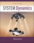
 Elements Of ElectromagneticsMechanical EngineeringISBN:9780190698614Author:Sadiku, Matthew N. O.Publisher:Oxford University Press
 Mechanics of Materials (10th Edition)Mechanical EngineeringISBN:9780134319650Author:Russell C. HibbelerPublisher:PEARSON
 Thermodynamics: An Engineering ApproachMechanical EngineeringISBN:9781259822674Author:Yunus A. Cengel Dr., Michael A. BolesPublisher:McGraw-Hill Education
 Control Systems EngineeringMechanical EngineeringISBN:9781118170519Author:Norman S. NisePublisher:WILEY
 Mechanics of Materials (MindTap Course List)Mechanical EngineeringISBN:9781337093347Author:Barry J. Goodno, James M. GerePublisher:Cengage Learning
 Engineering Mechanics: StaticsMechanical EngineeringISBN:9781118807330Author:James L. Meriam, L. G. Kraige, J. N. BoltonPublisher:WILEY