EBK SYSTEM DYNAMICS
3rd Edition
ISBN: 8220100254963
Author: Palm
Publisher: MCG
expand_more
expand_more
format_list_bulleted
Videos
Textbook Question
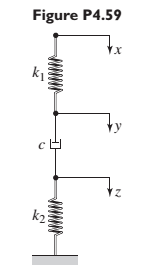
Chapter 4, Problem 4.59P
Find the transfer function
Expert Solution & Answer
Want to see the full answer?
Check out a sample textbook solution
Students have asked these similar questions
CORRECT AND DETAILED SOLUTION WITH COMPLETE FBD ONLY. I WILL UPVOTE.
9: The beam shown has a width of 80 mm and its allowable bending stress is not to exceed 120 MPa. Calculatethe required depth of the beam.
PROBLEM 4: A pre-stressed concrete pile of length L (m) is to be picked up by crane cables at two points, both equidistant
from the ends. If the concrete pile has a cross-sectional area of A (m²) and concrete has unit weight of Yc (kN/m³),
calculate the distance of the pick-up points from the end in terms of pile length. (Hint: to minimize the absolute maximum
moment, the maximum negative and maximum negative moments should be equal)
Correct and detailed solution only. Complete fbd. I will upvote.
Chapter 4 Solutions
EBK SYSTEM DYNAMICS
Ch. 4 - Prob. 4.1PCh. 4 - In the spring arrangement shown in Figure P4.2....Ch. 4 - In the arrangement shown in Figure P4.3, a cable...Ch. 4 - In the spring arrangement shown in Figure P4.4,...Ch. 4 - For the system shown in Figure P4.5, assume that...Ch. 4 - The two stepped solid cylinders in Figure P4.6...Ch. 4 - A table with four identical legs supports a...Ch. 4 - The beam shown in Figure P4.8 has been stiffened...Ch. 4 - Determine the equivalent spring constant of the...Ch. 4 - Compute the equivalent torsional spring constant...
Ch. 4 - Plot the spring force felt by the mass shown in...Ch. 4 - Calculate the expression for the natural frequency...Ch. 4 - Prob. 4.13PCh. 4 - Obtain the expression for the natural frequency of...Ch. 4 - 4.15 A connecting rod having a mass of 3.6 kg is...Ch. 4 - Calculate the expression for the natural frequency...Ch. 4 - For each of the systems shown in Figure P4.17, the...Ch. 4 - The mass m in Figure P4.18 is attached to a rigid...Ch. 4 - In the pulley system shown in Figure P4.19, the...Ch. 4 - Prob. 4.20PCh. 4 - Prob. 4.21PCh. 4 - Prob. 4.22PCh. 4 - In Figure P4.23, assume that the cylinder rolls...Ch. 4 - In Figure P4.24 when x1=x2=0 the springs are at...Ch. 4 - 4.25 In Figure P4.25 model the three shafts as...Ch. 4 - In Figure P4.26 when 1=2=0 the spring is at its...Ch. 4 - Prob. 4.27PCh. 4 - For the system shown in Figure P4.28, suppose that...Ch. 4 - For the system shown in Figure P4.29, suppose that...Ch. 4 - Prob. 4.30PCh. 4 - For Figure P4.31, the equilibrium position...Ch. 4 - Prob. 4.32PCh. 4 - Prob. 4.33PCh. 4 - 4.34 For Figure P4.34, assume that the cylinder...Ch. 4 - Use the Rayleigh method to obtain an expression...Ch. 4 - Prob. 4.36PCh. 4 - 4.37 Determine the natural frequency of the system...Ch. 4 - Determine the natural frequency of the system...Ch. 4 - Use Rayleigh's method to calculate the expression...Ch. 4 - Prob. 4.40PCh. 4 - Prob. 4.41PCh. 4 - Prob. 4.42PCh. 4 - The vibration of a motor mounted on the end of a...Ch. 4 - Prob. 4.44PCh. 4 - Prob. 4.45PCh. 4 - A certain cantilever beam vibrates at a frequency...Ch. 4 - Prob. 4.47PCh. 4 - 4.48 The static deflection of a cantilever beam is...Ch. 4 - Figure P4.49 shows a winch supported by a...Ch. 4 - Prob. 4.50PCh. 4 - Prob. 4.51PCh. 4 - Prob. 4.52PCh. 4 - 4.53 In Figure P4.53 a motor supplies a torque T...Ch. 4 - Derive the equation of motion for the lever system...Ch. 4 - Prob. 4.55PCh. 4 - Figure P4.56a shows a Houdaille damper, which is a...Ch. 4 - 4.57 Refer to Figure P4.57. Determine the...Ch. 4 - For the system shown in Figure P4.58, obtain the...Ch. 4 - Find the transfer function ZsXs for the system...Ch. 4 - Prob. 4.60PCh. 4 - Find the transfer function YsXs for the system...Ch. 4 - Prob. 4.62PCh. 4 - 4.63 In the system shown in Figure P4.63, the...Ch. 4 - Prob. 4.64PCh. 4 - Figure P4.65 shows a rack-and-pinion gear in which...Ch. 4 - Figure P4.66 shows a drive train with a spur-gear...Ch. 4 - Prob. 4.67PCh. 4 - Prob. 4.68PCh. 4 - Prob. 4.69PCh. 4 - Figure P4.70 shows a quarter-car model that...Ch. 4 - Prob. 4.71PCh. 4 - 4.72 Derive the equation of motion for the system...Ch. 4 - A boxcar moving at 1.3 m/s hits the shock absorber...Ch. 4 - For the systems shown in Figure P4.74, assume that...Ch. 4 - Refer to Figure P4.75a, which shows a ship’s...Ch. 4 - In this problem, we make all the same assumptions...Ch. 4 - Refer to Figure P4.79a, which shows a water tank...Ch. 4 - The “sky crane” shown on the text cover was a...Ch. 4 - Prob. 4.81PCh. 4 - Prob. 4.82PCh. 4 - Suppose a mass in moving with a speed 1 becomes...Ch. 4 - Consider the system shown in Figure 4.6.3. Suppose...Ch. 4 - Prob. 4.86PCh. 4 - Figure P4.87 shows a mass m with an attached...Ch. 4 - Figure P4.88 represents a drop forging process....Ch. 4 - Refer to Figure P4.89. A mass m drops from a...Ch. 4 - Prob. 4.90PCh. 4 - (a) Obtain the equations of motion of the system...Ch. 4 - Refer to part (a) of Problem 4.90. Use MATLAB to...Ch. 4 - Refer to Problem 4.91. Use MATLAB to obtain the...Ch. 4 - 4.94 (a) Obtain the equations of motion of the...Ch. 4 -
4.95 (a) Obtain the equations of motion of the...
Knowledge Booster


Learn more about
Need a deep-dive on the concept behind this application? Look no further. Learn more about this topic, mechanical-engineering and related others by exploring similar questions and additional content below.Similar questions
- 3: Given the shear diagram of the simply supported beam shown, properly illustrate the load and bendingmoment diagram considering that the beam carries a 5 kN-m clockwise moment at C.arrow_forwardCORRECT AND DETAILED SOLUTION WITH COMPLETE FBD ONLY. I WILL UPVOTE. 8: A 2-m cantilever beam with cross-sectionshown carries a uniformly distributed load of 12 kN/m. Dueto fixture requirements, a hole of diameter 150 mm isremoved from the cross-section. (a) Calculate themaximum normal compressive stress. (b) Calculate themaximum normal tensile stress. (c) Calculate anddetermine the state of stress at the lowest point of thecircular hole.arrow_forward5: A 12-m simply supported bridge is constructed with 100-mm concrete slab deck supported by precastconcrete stringers spaced 800 mm on center. Analyze the stringers when subjected to a moving load consisting of 3 evenly spaced axle loads at 3 m and equivalent to 20 kN, 30 kN and 40 kN respectively. The self-weight of the stringers is 8.5 kN/m and the concrete deck has a unit weight of 24 kN/m3 . Neglect all other superimposed loads. Calculate: (a) the maximum shear force in the stringers; (b) the maximum bending moment in the stringers.arrow_forward
- 2: The given continuous beam supports a uniform load with magnitude w. It has an internal hinge at C. (a)Calculate the maximum uniform load w that the beam can carry if it has a moment capacity of 65 kN-m for negativebending; (b) Calculate the maximum uniform load w that the beam can carry if it has a moment capacity of 85 kN-m forpositive bending; (c) Calculate the maximum uniform load w that the beam can carry if it has a shear capacity of 40 kN.arrow_forwardCORRECT AND DETAILED SOLUTION WITH COMPLETE FBD ONLY. I WILL UPVOTE. 10: A wooden beam 150 mm wide by 300 mm deep is loaded asshown. The maximum flexural stress developed is 8 MN/m2. (a) Computethe maximum moment the beam section can resist. (b) Determine themaximum value of the uniform load w in kN/m. (c) Calculate the maximumvalue of the concentrated load P.arrow_forwardThis is a tilt and rotation question. Here are notes attached for reference. ONLY UPLOAD A SOLUTION IF YOU ARE SURE ABOUT THE ANSWER PLEASE.arrow_forward
- (b): Let us first consider controlling the orbit of deputy spacecraft to rendezvous with chief spacecraft. Define x = [r] and x = x = R to represent the deputy orbital state and its target (= chief orbit) in Cartesian coordinates, respectively. The control input is thruster acceleration, u € R³, in the ECI frame. Denote the relative state by dx = x-x. Table 2 summarize the initial orbital elements. Table 2: Keplerian orbital elements at epoch (t = 0) for deputy and chief about Earth (ECI frame) Orbital element Deputy Unit Chief semi-major axis ad = 11500 ac 10000 km eccentricity inclination ed = 0.15 id=35 ee = 0.3 i = 50 degree right ascension of ascending node d = 50 Ως = 50 degree argument of periapsis true anomaly at epoch Wd Vd= 0 = 40 We = 40 degree Ve=0 degree (b.1): Derive the error dynamics of our system in ECI frame under the influence of u. (b.2): Consider a candidate Lyapunov function V = ½dr¹ K₁dr+dv₁dv, where K₁ = K, and K, > 0. Discuss the positive definiteness of V, and…arrow_forwardOne image show problem c.1 and c.2 that I need help with. The second image shows the lyapunov function and its derivative but it is NOT the same function that is given in problem. I have attached that image as an example.arrow_forwardThis is a tilt and rotation question. Here are notes attached for reference.arrow_forward
- The crate of mass m is supported on a cart of negligible mass as shown in (Figure 1). Determine the maximum force P that can be applied a distance d from the cart bottom without causing the crate to tip on the cart. Express your answer in terms of some, all, or none of the variables b, d, h, m, and the acceleration due to gravity g. P B harrow_forwardConsider a pair of pipes running in parallel, through which 1200 GPM flows, which have thefollowing features:Pipe 1: Carbon Steel, Schedule 40, 8" Diameter, 1200 GPM, Water at 44°F, Fittings:2 tees, 2 butterfly valves, 2 pressure gauges with their respective ball valves, 1 valvemotorized balloon. All valves are completely open. Length of the pipe is 6 feet. Pipe 2: consists of a carbon steel bypass pipe, schedule 40, diameter of 4",with the following accessories: 2 elbows long radius of 90° and an open globe valve.The length of the pipe is 10 feet. a) Determine the flow rate in each pipe.b) The pressure drop.arrow_forward1-ft3 of air is contained in a spring-loaded piston-cylinder device. The spring constant is 6 lbf/in, and thepiston diameter is 12 in. When no force is exerted by the spring on the piston, the state of the air is 250 psiaand 450◦F. This device is now cooled until the volume is one-third its original size. Determine the changein the specific internal energy and enthalpy of the air.arrow_forward
arrow_back_ios
SEE MORE QUESTIONS
arrow_forward_ios
Recommended textbooks for you
 Elements Of ElectromagneticsMechanical EngineeringISBN:9780190698614Author:Sadiku, Matthew N. O.Publisher:Oxford University Press
 Mechanics of Materials (10th Edition)Mechanical EngineeringISBN:9780134319650Author:Russell C. HibbelerPublisher:PEARSON
 Thermodynamics: An Engineering ApproachMechanical EngineeringISBN:9781259822674Author:Yunus A. Cengel Dr., Michael A. BolesPublisher:McGraw-Hill Education
 Control Systems EngineeringMechanical EngineeringISBN:9781118170519Author:Norman S. NisePublisher:WILEY
 Mechanics of Materials (MindTap Course List)Mechanical EngineeringISBN:9781337093347Author:Barry J. Goodno, James M. GerePublisher:Cengage Learning
 Engineering Mechanics: StaticsMechanical EngineeringISBN:9781118807330Author:James L. Meriam, L. G. Kraige, J. N. BoltonPublisher:WILEY
Elements Of Electromagnetics
Mechanical Engineering
ISBN:9780190698614
Author:Sadiku, Matthew N. O.
Publisher:Oxford University Press
Mechanics of Materials (10th Edition)
Mechanical Engineering
ISBN:9780134319650
Author:Russell C. Hibbeler
Publisher:PEARSON
Thermodynamics: An Engineering Approach
Mechanical Engineering
ISBN:9781259822674
Author:Yunus A. Cengel Dr., Michael A. Boles
Publisher:McGraw-Hill Education
Control Systems Engineering
Mechanical Engineering
ISBN:9781118170519
Author:Norman S. Nise
Publisher:WILEY
Mechanics of Materials (MindTap Course List)
Mechanical Engineering
ISBN:9781337093347
Author:Barry J. Goodno, James M. Gere
Publisher:Cengage Learning
Engineering Mechanics: Statics
Mechanical Engineering
ISBN:9781118807330
Author:James L. Meriam, L. G. Kraige, J. N. Bolton
Publisher:WILEY
How to balance a see saw using moments example problem; Author: Engineer4Free;https://www.youtube.com/watch?v=d7tX37j-iHU;License: Standard Youtube License