
Concept explainers
Videos
Whether the equation of motion of the pendulum and the system is stable, neutrally stable or unstable.
Answer to Problem 4.68P
Explanation of Solution
Given:
A spring with stiffness k, and a damper with damping coefficient c, are attached to a pendulum of mass, m.
Concept used:
For an objects’ planar motion which rotates only about an axis perpendicular to the plane, the equation of motion can be written down using Newton’s Second Law.
Equation of Motion:
Where
Let the angular displacement be
The angular velocity,
Hence, the equation of motion of this object can be rewritten by substituting,
To find the equation of motion, the required unknowns are
The mass moment of Inertia, I about a specified reference axis is given as:
Where r = distance from the reference axis to mass element
Mass moment of Inertia of a rotating pendulum =
In this question, the distance from the reference axis to the mass element, r = L. Substituting this to the above equation gives:
Moments = Perpendicular Force
In this question, the pivot is point O.
Total moments about O = Moments of mass, m + Moments of spring element + Moments of the damper
Free body diagram of the system:
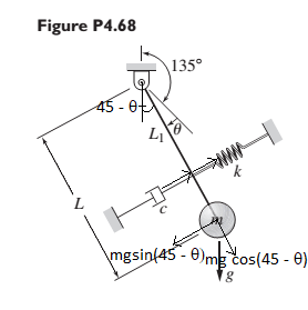
Moments of mass, m:
The force mg can be resolved to two components,
The force causing the moments will be
Moments =
Moments of the spring element:
Using the Hooke’s Law, a linear force-deflection model can be written,
Where f = restoring force
x = compression or extension distance
k = Spring constant or stiffness
Here the extension distance,
Hence the moments due to spring element =
Moments of the Damper:
The linear model for the force applied by the damper is:
Where f = damping force
v = relative velocity
c = damping coefficient
Here the force,
The distance between the pivot, O and the force applied =
Hence Moments of the damper =
Taking clockwise to be positive and substitute the above expressions to the following equation,
Total moments about O = Moments of mass, m + Moments of spring element + Moments of the damper
Total moments =
Derivation of Equation of Motion:
Substitute
Assuming
The differentiation of a constant is 0, hence the moment due to the force applied by the damper becomes 0.
Simplifying the equation further:
The equation of motion of the system is
When
When
Want to see more full solutions like this?
Chapter 4 Solutions
System Dynamics


- Part A: Suppose you wanted to drill a 1.5 in diameter hole through a piece of 1020 cold-rolled steel that is 2 in thick, using an HSS twist drill. What values if feed and cutting speed will you specify, along with an appropriate allowance? Part B: How much time will be required to drill the hole in the previous problem using the HSS drill?arrow_forward1.1 m 1.3 m B 60-mm diameter Brass 40-mm diameter Aluminum PROBLEM 2.52 - A rod consisting of two cylindrical portions AB and BC is restrained at both ends. Portion AB is made of brass (E₁ = 105 GPa, α = 20.9×10°/°C) and portion BC is made of aluminum (Ę₁ =72 GPa, α = 23.9×10/°C). Knowing that the rod is initially unstressed, determine (a) the normal stresses induced in portions AB and BC by a temperature rise of 42°C, (b) the corresponding deflection of point B.arrow_forward30 mm D = 40 MPa -30 mm B C 80 MPa PROBLEM 2.69 A 30-mm square was scribed on the side of a large steel pressure vessel. After pressurization, the biaxial stress condition at the square is as shown. For E = 200 GPa and v=0.30, determine the change in length of (a) side AB, (b) side BC, (c) diagnonal AC.arrow_forward
- Please solve in detail this problem thank youarrow_forward0,5 mm 450 mm 350 mm Bronze A = 1500 mm² E = 105 GPa प 21.6 × 10-PC Aluminum A = 1800 mm² £ = 73 GPa = a 23.2 × 10-PC PROBLEM 2.58 Knowing that a 0.5-mm gap exists when the temperature is 24°C, determine (a) the temperature at which the normal stress in the aluminum bar will be equal to -75 MPa, (b) the corresponding exact length of the aluminum bar.arrow_forward0.5 mm 450 mm -350 mm Bronze Aluminum A 1500 mm² A 1800 mm² E 105 GPa E 73 GPa K = 21.6 X 10 G < = 23.2 × 10-G PROBLEM 2.59 Determine (a) the compressive force in the bars shown after a temperature rise of 82°C, (b) the corresponding change in length of the bronze bar.arrow_forward
- The truss shown below sits on a roller at A and a pin at E. Determine the magnitudes of the forces in truss members GH, GB, BC and GC. State whether they are in tension or compression or are zero force members.arrow_forwardA weight (W) hangs from a pulley at B that is part of a support frame. Calculate the maximum possible mass of the weight if the maximum permissible moment reaction at the fixed support is 100 Nm. Note that a frictionless pin in a slot is located at C.arrow_forwardIt is the middle of a winter snowstorm. Sally and Jin take shelter under an overhang. The loading of the snow on top of the overhang is shown in the figure below. The overhang is attached to the wall at points A and B with pin supports. Another pin is at C. Determine the reactions of the pin supports at A and B. Express them in Cartesian vector form.arrow_forward
- Recall that the CWH equation involves two important assumptions. Let us investigate how these assumptions affect the accuracy of state trajectories under the control inputs optimized in (a) and (b). (c.1): Discuss the assumptions about the chief and deputy orbits that are necessary for deriving CWH.arrow_forwardPROBLEM 2.50 1.8 m The concrete post (E-25 GPa and a = 9.9 x 10°/°C) is reinforced with six steel bars, each of 22-mm diameter (E, = 200 GPa and a, = 11.7 x 10°/°C). Determine the normal stresses induced in the steel and in the concrete by a temperature rise of 35°C. 6c " 0.391 MPa 240 mm 240 mm 6₁ = -9.47 MPaarrow_forwardFor some viscoelastic polymers that are subjected to stress relaxation tests, the stress decays with time according to a(t) = a(0) exp(-4) (15.10) where σ(t) and o(0) represent the time-dependent and initial (i.e., time = 0) stresses, respectively, and t and T denote elapsed time and the relaxation time, respectively; T is a time-independent constant characteristic of the material. A specimen of a viscoelastic polymer whose stress relaxation obeys Equation 15.10 was suddenly pulled in tension to a measured strain of 0.5; the stress necessary to maintain this constant strain was measured as a function of time. Determine E (10) for this material if the initial stress level was 3.5 MPa (500 psi), which dropped to 0.5 MPa (70 psi) after 30 s.arrow_forward
 Elements Of ElectromagneticsMechanical EngineeringISBN:9780190698614Author:Sadiku, Matthew N. O.Publisher:Oxford University Press
 Mechanics of Materials (10th Edition)Mechanical EngineeringISBN:9780134319650Author:Russell C. HibbelerPublisher:PEARSON
 Thermodynamics: An Engineering ApproachMechanical EngineeringISBN:9781259822674Author:Yunus A. Cengel Dr., Michael A. BolesPublisher:McGraw-Hill Education
 Control Systems EngineeringMechanical EngineeringISBN:9781118170519Author:Norman S. NisePublisher:WILEY
 Mechanics of Materials (MindTap Course List)Mechanical EngineeringISBN:9781337093347Author:Barry J. Goodno, James M. GerePublisher:Cengage Learning
 Engineering Mechanics: StaticsMechanical EngineeringISBN:9781118807330Author:James L. Meriam, L. G. Kraige, J. N. BoltonPublisher:WILEY