
Concept explainers
Videos
Our pipelined design is a bit unrealistic in that we have two write ports for the register file, but only the popq instruction requires two simultaneous writes to the register file. The other instructions could therefore use a single write port, sharing this for writing valE and valM. The following figure shows a.modified version of the write-back logic, in which we merge the write-back register IDs (W_dstE and W_dstM) into a single signal W_dstE and the write-back values (W_valE and W_yalM) into a single signal w_valE:
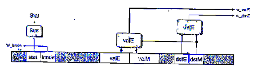
The logic for performing the merges is written in HCL as follows:
## Set E port register ID
word w_datE = [
## writing from valM
W_dstH != RNONE : W_dstM;
1: W_dstE;
};
# Set E port value
word w_valE - [
W_dstM != RNONE : W_valM;
1 : W_valE;
};
The control for these multiplexors is determined by dstE—when it indicates there is some register, then it selects the value for port E, and otherwise it selects the value for port M.
In the simulation model, we can then disable register port M, as shown by the following HCL code:
## Disable register port M
## Set M port register ID
word w_dstM = RNONE;
## Set M port value
word w_valM = 0;
The challenge then becomes to devise a way to handle popq. One method is to use the control logic to dynamically process the instruction popq rA so that it has the same effect as the two-instruction sequence
iaddq $8, %rsp
mrmovq -8 (%rsp) , rA
(See Practice Problem 4.3 for a description of the iaddq instruction.) Note the ordering of the two instructions to make sure popq %rsp works properly. You can do this by having the logic in the decode stage treat popq the same as it would the iaddq listed above, exceptthat it predicts the next PC to be equal to the current PC. On the next cycle, the popq instruction is refetched, but the instruction code is converted to a special value IPOP2. This is treated as a special instruction that has the same behavior as the mrmovq instruction listed above.
The file pipe-lw. hcl contains the modified write port logic described above. It contains a declaration of the constant IPOP2 having hexadecimal value E. It also contains the definition of a signal f_icode that generates the (code field for pipeline register D. This definition can be modified to insert the instruction code IPOP2 the second time the popq instruction is fetched. The 1-ICL file also contains a declaration of the signal f_pc, the value of the program counter generated in the fetch stage by the block labeled "Select PC" (Figure 4.57).
Modify the control logic in this the to process popq instructions in the manner we have described. See the lab material for directions on how to generate a simulator for your solution and how to test it.
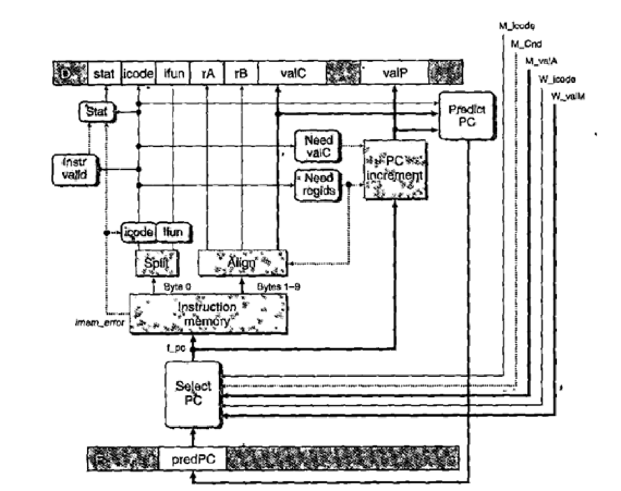
Figure 4.57 PIPE PC selection and fetch logic. Within the one cycle time limit, the processor can only predict the address of the next instruction.
Want to see the full answer?
Check out a sample textbook solution
Chapter 4 Solutions
Computer Systems: A Programmer's Perspective Plus Mastering Engineering With Pearson Etext -- Access Card Package (3rd Edition)
Additional Engineering Textbook Solutions
Java: An Introduction to Problem Solving and Programming (8th Edition)
Mechanics of Materials (10th Edition)
Electric Circuits. (11th Edition)
Web Development and Design Foundations with HTML5 (8th Edition)
Starting Out with Java: From Control Structures through Data Structures (4th Edition) (What's New in Computer Science)
Starting Out with Programming Logic and Design (5th Edition) (What's New in Computer Science)


- Complete the JavaScript function addPixels () to calculate the sum of pixelAmount and the given element's cssProperty value, and return the new "px" value. Ex: If helloElem's width is 150px, then calling addPixels (hello Elem, "width", 50) should return 150px + 50px = "200px". SHOW EXPECTED HTML JavaScript 1 function addPixels (element, cssProperty, pixelAmount) { 2 3 /* Your solution goes here *1 4 } 5 6 const helloElem = document.querySelector("# helloMessage"); 7 const newVal = addPixels (helloElem, "width", 50); 8 helloElem.style.setProperty("width", newVal); [arrow_forwardSolve in MATLABarrow_forwardHello please look at the attached picture. I need an detailed explanation of the architecturearrow_forward
- Information Security Risk and Vulnerability Assessment 1- Which TCP/IP protocol is used to convert the IP address to the Mac address? Explain 2-What popular switch feature allows you to create communication boundaries between systems connected to the switch3- what types of vulnerability directly related to the programmer of the software?4- Who ensures the entity implements appropriate security controls to protect an asset? Please do not use AI and add refrencearrow_forwardFind the voltage V0 across the 4K resistor using the mesh method or nodal analysis. Note: I have already simulated it and the value it should give is -1.714Varrow_forwardResolver por superposicionarrow_forward
- Describe three (3) Multiplexing techniques common for fiber optic linksarrow_forwardCould you help me to know features of the following concepts: - commercial CA - memory integrity - WMI filterarrow_forwardBriefly describe the issues involved in using ATM technology in Local Area Networksarrow_forward
- For this question you will perform two levels of quicksort on an array containing these numbers: 59 41 61 73 43 57 50 13 96 88 42 77 27 95 32 89 In the first blank, enter the array contents after the top level partition. In the second blank, enter the array contents after one more partition of the left-hand subarray resulting from the first partition. In the third blank, enter the array contents after one more partition of the right-hand subarray resulting from the first partition. Print the numbers with a single space between them. Use the algorithm we covered in class, in which the first element of the subarray is the partition value. Question 1 options: Blank # 1 Blank # 2 Blank # 3arrow_forward1. Transform the E-R diagram into a set of relations. Country_of Agent ID Agent H Holds Is_Reponsible_for Consignment Number $ Value May Contain Consignment Transports Container Destination Ф R Goes Off Container Number Size Vessel Voyage Registry Vessel ID Voyage_ID Tonnagearrow_forwardI want to solve 13.2 using matlab please helparrow_forward
 Systems ArchitectureComputer ScienceISBN:9781305080195Author:Stephen D. BurdPublisher:Cengage Learning
 Principles of Information Systems (MindTap Course...Computer ScienceISBN:9781285867168Author:Ralph Stair, George ReynoldsPublisher:Cengage Learning
 EBK JAVA PROGRAMMINGComputer ScienceISBN:9781337671385Author:FARRELLPublisher:CENGAGE LEARNING - CONSIGNMENT
 COMPREHENSIVE MICROSOFT OFFICE 365 EXCEComputer ScienceISBN:9780357392676Author:FREUND, StevenPublisher:CENGAGE L
 C++ for Engineers and ScientistsComputer ScienceISBN:9781133187844Author:Bronson, Gary J.Publisher:Course Technology Ptr
 Enhanced Discovering Computers 2017 (Shelly Cashm...Computer ScienceISBN:9781305657458Author:Misty E. Vermaat, Susan L. Sebok, Steven M. Freund, Mark Frydenberg, Jennifer T. CampbellPublisher:Cengage Learning