EBK APPLIED FLUID MECHANICS
7th Edition
ISBN: 8220100668340
Author: UNTENER
Publisher: PEARSON
expand_more
expand_more
format_list_bulleted
Textbook Question
Chapter 4, Problem 4.52PP
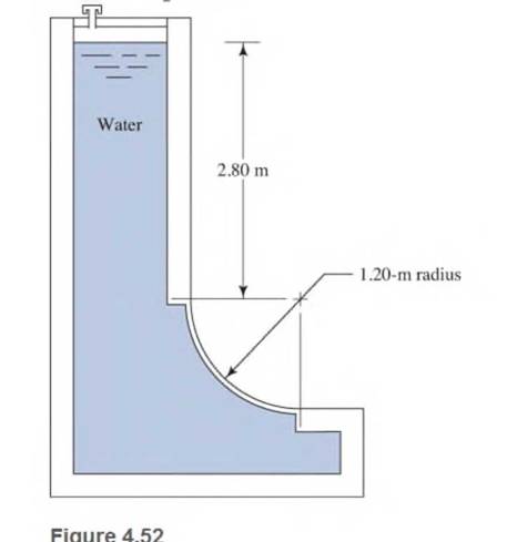
Use Fig .4.52. The surface is
long
Expert Solution & Answer
Want to see the full answer?
Check out a sample textbook solution
Students have asked these similar questions
answer please
amination)
Question 1
Consider the bar, shown in Figure 1, that undergoes axial displacement due to both a distributed load
and a point force. The bar is of cross-sectional area A = 1.103 m2, and has a modulus of elasticity
E = 100 GPa.
1(x) = 5 kN/m
10 kN
X
x=0.0
x=2.0
2.0m
Figure 1: Bar domain with varying distributed forces.
a) The general form of the governing equations describing the bar's displacement, u(x), is given by,
d
(AE du(x)) + 1(x) = 0.
dx
dx
What are the accompanying boundary conditions for this bar?
MacBook Air
a
会
DII
F5
F6
F7
F8
80
F3
F4
0/
20
[8 marksl
8
FO
Answer B
Chapter 4 Solutions
EBK APPLIED FLUID MECHANICS
Ch. 4 - figure 4.2 shows a vacuum tank with a flat...Ch. 4 - The flat left end of the tank shown in Fig. 4.21...Ch. 4 - An exhaust system for a room creates a partial...Ch. 4 - A piece of 14 -in Schedule 40 pipe is used as a...Ch. 4 - A pressure relief valve is designed so that the...Ch. 4 - A gas-powered cannon shoots projectiles by...Ch. 4 - The egress hatch of a manned spacecraft is...Ch. 4 - A tank containing liquid ammonia at 77F has a flat...Ch. 4 - The bottom of a laboratory vat has a hole in it to...Ch. 4 - A simple shower for remote locations is designed...
Ch. 4 - Calculate the total force on the bottom of the...Ch. 4 - If the length of the tank in Fig. 4.24 is 1.2m,...Ch. 4 - An observation port in a small submarine is...Ch. 4 - A rectangular gate is installed in a vertical wall...Ch. 4 - '4.15 A vat has a sloped side, as shown in Fig....Ch. 4 - The wall shown in Fig. 4.28 is 20 ft long, (a)...Ch. 4 - If the wall in Fig. 4.29 is 4m long, calculate the...Ch. 4 - Refer to Fig. 4.30Ch. 4 - Refer to Fig. 4.31Ch. 4 - Refer to Fig.4.32Ch. 4 - Refer to Fig 4.33Ch. 4 - Refer to Fig. 4.34Ch. 4 - Refer to Fig. 4.35 (?Ch. 4 - Swimming poo!WilierGlasswindow2 ft diameterFigure...Ch. 4 - 4.25 Refer to Fig 4.37Ch. 4 - Refer to Fig.4.38Ch. 4 - Refer to Fig.4.39Ch. 4 - Refer to Fig.4.40Ch. 4 - Refer to Fig 4.41Ch. 4 - figure 4.42i5 shows a gasoline tank filled into...Ch. 4 - If the tank in Fig. 4.42 is filled just to the...Ch. 4 - If the tank in Fig. 4.42 is only half full of...Ch. 4 - For the water tank shown in Fig. 4.43, compute the...Ch. 4 - For the water tank shown in Fig. 4.43, compute the...Ch. 4 - For the water tank shown in Fig. 4.43, compute the...Ch. 4 - For the orange-drink tank shown in Fig. 4.32,...Ch. 4 - For the orange-drink tank shown in Fig. 4.32,...Ch. 4 - For the oil tank shown in Fig. 4.35, compute the...Ch. 4 - For the oil tank shown in Fig. 4.35; compute the...Ch. 4 - figure 4.44 shows a rectangular gate holding water...Ch. 4 - figure 4.45 shows a gate hinged at its bottom and...Ch. 4 - figure 4.46 shows a tank of water with a circular...Ch. 4 - Repeat Problem 4.19(Fig. 4.31), except that the...Ch. 4 - Repeat Problem 4.22 (Fig. 4.32), except that the...Ch. 4 - Repeat Problem 4.26 (Fig. 4.38 ). except that the...Ch. 4 - Repeat Problem 4.28 (Fig. 4.40 ), except that the...Ch. 4 - Use Fig 4.47. The surface is 2.00m long.Ch. 4 - Use Fig.4.48. The surface is 2.50m long.Ch. 4 - Use Fig.4.49. The surface is 5.00 ft longCh. 4 - Use Fig.4.50. The surface is 4.50 ft long.Ch. 4 - Use Fig.4.51.The surface is 4.00 m long.Ch. 4 - Use Fig .4.52. The surface is 1.50m longCh. 4 - Use Fig. 4.53. The surface is 1.50m long.Ch. 4 - Use Fig. 4.54. The surface is 60 in longCh. 4 - Repeat Problem 4.47 using Fig. 4.47, except that...Ch. 4 - Repeat Problem 4.48 using Fig. 4.48, except that...Ch. 4 - The tank in Fig. 4.55 has a view port in the...Ch. 4 - Insulated concrete forms (ICFs) are becoming more...Ch. 4 - Lacks are installed in rivers to allow boats to...Ch. 4 - When a dam is installed in a river that has...Ch. 4 - A wealthy eccentric is interested in having an...Ch. 4 - A pneumatic cylinder like the one shown in Fig....Ch. 4 - Determine the magnitude and the location of the...Ch. 4 - For the hinged gate shown in Fig. 4.61, determine...Ch. 4 - Prob. 4.65PPCh. 4 - Write a program to solve Problem 4.41 with any...Ch. 4 - Write a program to solve Problem 4.42 (Fig. 4.46)...Ch. 4 - Write a program to solve curved surface problems...Ch. 4 - For Program 1, cause the depth h to vary over some...
Knowledge Booster
Learn more about
Need a deep-dive on the concept behind this application? Look no further. Learn more about this topic, mechanical-engineering and related others by exploring similar questions and additional content below.Similar questions
- CFD help Figure 3: Advection equation, solution for three different timesteps. Q1) Provide an explanation what conditions and numerical setup could explain the curves. Identify which of the three curves is the first, second and third timestep.arrow_forwardanswer pleasearrow_forwardFigure 3 shows the numerical solution of the advection equation for a scalar u along x at three consecutive timesteps. 1.0 0.8- 0.6 0.4- 0.2 0.0 00 -0.2 -0.4 -0.6- 3.0 3.5 4.0 4.5 5.0 5.5 6.0 6.5 Figure 3: Advection equation, solution for three different timesteps.arrow_forward
- Question 2 Figure 3 shows the numerical solution of the advection equation for a scalar u along x at three consecutive timesteps. 1.0 0.8- 0.6- 0.4- 0.2- 0.0- -0.2- -0.4- -0.6 3.0 3.5 4.0 4.5 5.0 5.5 6.0 6.5 Figure 3: Advection equation, solution for three different timesteps. a) Provide an explanation what conditions and numerical setup could explain the curves. Identify which of the three curves is the first, second and third timestep. b) Consider explicit schemes with central and upwind discretisations. Explain how each of these candidate discretisations could produce the behaviour shown in Figure 3. c) Determine the CFL number that was used in the simulation for each of the candidate schemes for all possible updates. Assume that the timestep and mesh-width used are constant. Read the data to two digits of accuracy from Figure 4 shown at the end of the question, which is an enlarged version of Figure 3. Demonstrate your method and input data for one calculation, but then use a…arrow_forwardanswer pleasearrow_forwardProvide an explanation what conditions and numerical setup could explain the curves. Identify which of the three curves is the first. second and third timestep.arrow_forward
- What are the accompanving boundary conditions for this bar?arrow_forward1.1 Consider the fireclay brick wall of Example 1.1 that is operating under different thermal conditions. The tem- perature distribution, at an instant in time, is T(x) = a+ bx where a 1400 K and b = -1000 K/m. Determine the heat fluxes, q", and heat rates, q, at x = 0 and x = L. Do steady-state conditions exist?arrow_forward2.4 To determine the effect of the temperature dependence of the thermal conductivity on the temperature dis- tribution in a solid, consider a material for which this dependence may be represented as k = k₁ + aT where k, is a positive constant and a is a coefficient that may be positive or negative. Sketch the steady-state temperature distribution associated with heat transfer in a plane wall for three cases corresponding to a > 0, a = 0, and a < 0.arrow_forward
arrow_back_ios
SEE MORE QUESTIONS
arrow_forward_ios
Recommended textbooks for you
 International Edition---engineering Mechanics: St...Mechanical EngineeringISBN:9781305501607Author:Andrew Pytel And Jaan KiusalaasPublisher:CENGAGE L

International Edition---engineering Mechanics: St...
Mechanical Engineering
ISBN:9781305501607
Author:Andrew Pytel And Jaan Kiusalaas
Publisher:CENGAGE L
Physics 33 - Fluid Statics (1 of 10) Pressure in a Fluid; Author: Michel van Biezen;https://www.youtube.com/watch?v=mzjlAla3H1Q;License: Standard YouTube License, CC-BY