
Concept explainers
Videos
The voltage source shown in Figure P4.51 is called a ramp function Assume that
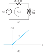
Figure P4.51
Want to see the full answer?
Check out a sample textbook solution
Chapter 4 Solutions
EBK ELECTRICAL ENGINEERING
Additional Engineering Textbook Solutions
Elementary Surveying: An Introduction To Geomatics (15th Edition)
Modern Database Management
Thermodynamics: An Engineering Approach
Concepts Of Programming Languages
Electric Circuits. (11th Edition)
Management Information Systems: Managing The Digital Firm (16th Edition)


- 2. Write an expression of the two sinusoidal voltage waveforms whose effective value is 7.071 V and whose phase difference is 90 degrees. Draw the phasor of those two sinusoidal waveforms in the complex plane.arrow_forward2. Determine developed torque and shaft torque of 220-V, 4-pole series motor with 800 conductors wave-connected supplying a load of 8.2kW by taking 45A from the mains. The flux per pole is 25 mWb and its armature circuit resistance is 0.60. Ans.[143.25 Nm, 135.25 Nm]arrow_forward7. resistance): The practical capacitor can be simplified as the model below (ESR: equivalent series 10 μF ESR W From a datasheet, it is known that a 10 µF aluminum electrolytic capacitor has an impedance of 2800 mOhm at the 100 kHz testing condition. (1) Calculate the ESR under the above testing condition; (2) Calculate the phase shift between the voltage and current at 100 Hz and 10k Hz sinusoidal excitation conditions.arrow_forward
- 5. A circuit has the following AC sources: y₁ = 5 cos(wt + 30°), y₂ = 4 cos(2wt + 120°), y3 = 3 cos(4wt - 60°), y4 = 6 cos(2wt - 120°), y = 2√2cos(wt - 60°): (1) Identify fundamental sources and harmonics. (2) Using phasor approach to simplify y₁ + y2 y3 y4 y5 as much as possible.arrow_forward6. A practical 10 μH wire wounded inductor has a series parasitic resistance of 0.4 Ohm, as shown in the figure below. a 10 pH 0.4 Ω W° b If an AC current y₁ = 4cos (20πt + 60°) is supplied to this inductor, (1) calculate the voltage across the inductor terminals a and b. (2) express the inductor terminal voltage and current in the complex plane. (3) calculate the phase shift between inductor terminal voltage and current If an AC current y₂ = 4cos (2000лt + 60°) is supplied to this inductor, (4) calculate the voltage across the inductor terminals a and b. (5) express the inductor terminal voltage and current in the complex plane. (6) calculate the phase shift between inductor terminal voltage and currentarrow_forward1. As shown below, an LED lightbulb is connected to the grid power. The LED lightbulb has a rated power of 15 W, and the gird voltage is 120 V 60 Hz. Based on the above information (1) what is the peak value and effective value of the current flowing through the LED light bulb, (2) write an expression of the current flowing through the LED light bulb.arrow_forward
- Q4: Determine the reactions at support A in structure shown in figure below. 4 kN/m 2.5 kN/m 9 m 4 marrow_forward4. A circuit has three AC sources: y₁ = 5cos(wt + 30°), y2 = 4cos(wt + 120°), y3 2cos(wt 60°), calculating: = (1) y₁ + y2 y3, and express the addition in the complex plane using phasors. (2) y1 y2 y3, and express the subtraction in the complex plane using phasorsarrow_forwardDon't use ai to answer I will report you answerarrow_forward
- A 50-HP, 600-V compound motor, taking 80 A, operates at a speed of 495 r.p.m. at full-load. If the flux per pole is 9.1 x 10⁶ Maxwells and the armature resistance is 0.01502, the field resistances are 0.006 ohms and 300 ohms. Calculate: a. Field currents and the armature current b. the counter emf c. the rotational loss Ans.[2A,78A,593.362 V,8982.236 W]arrow_forward1. A 600-V, 150-HP, 600 r.p.m. d.c. series motor has an armature and series field resistance of 0.120 and 0.040, respectively. The full-load current is 200A. (a) Find the back e.m.f. at full-load. (b) Find the armature developed power and torque at full-load. Ans. [568V, 1808.13 N.m]arrow_forward3. An electrical device shown below has the following depicted voltage and current definition. The current in and the voltage vin for a certain period is recorded as shown in the bottom picture. (1) In different periods from 0 to time T4, determine if the electrical device works as a load or a source. iin + iin Vin Electrical Device 0 T₁ T2 T3 ΤΑ t Vin T2 ΤΑ tarrow_forward
 Introductory Circuit Analysis (13th Edition)Electrical EngineeringISBN:9780133923605Author:Robert L. BoylestadPublisher:PEARSON
 Delmar's Standard Textbook Of ElectricityElectrical EngineeringISBN:9781337900348Author:Stephen L. HermanPublisher:Cengage Learning
 Programmable Logic ControllersElectrical EngineeringISBN:9780073373843Author:Frank D. PetruzellaPublisher:McGraw-Hill Education
 Fundamentals of Electric CircuitsElectrical EngineeringISBN:9780078028229Author:Charles K Alexander, Matthew SadikuPublisher:McGraw-Hill Education
 Electric Circuits. (11th Edition)Electrical EngineeringISBN:9780134746968Author:James W. Nilsson, Susan RiedelPublisher:PEARSON
 Engineering ElectromagneticsElectrical EngineeringISBN:9780078028151Author:Hayt, William H. (william Hart), Jr, BUCK, John A.Publisher:Mcgraw-hill Education,