
Videos
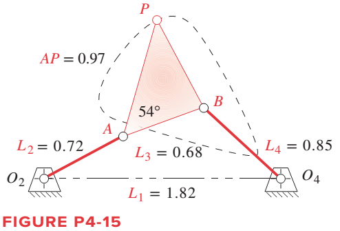
For the linkage in Figure P4-15, find its limit (toggle) positions in terms of the angle of link
Want to see the full answer?
Check out a sample textbook solution
Chapter 4 Solutions
DESIGN OF MACHINERY


- CORRECT AND DETAILED HANDWRITTEN SOLUTION WITH FBD ONLY. I WILL UPVOTE THANK YOU. CORRECT ANSWER IS ALREADY PROVIDED. 5: A 12-m simply supported bridge is constructed with 100-mm concrete slab deck supported by precastconcrete stringers spaced 800 mm on center. Analyze the stringers when subjected to a moving load consisting of 3 evenly spaced axle loads at 3 m and equivalent to 20 kN, 30 kN and 40 kN respectively. The self-weight of the stringers is 8.5 kN/m and the concrete deck has a unit weight of 24 kN/m3 . Neglect all other superimposed loads. Calculate: (a) the maximum shear force in the stringers; (b) the maximum bending moment in the stringers. Answer: Vmax = 135.020 KN, Mmax = 477.388 KN-Marrow_forwardCORRECT AND DETAILED HANDWRITTEN SOLUTION WITH FBD ONLY. I WILL UPVOTE THANK YOU. CORRECT ANSWER IS ALREADY PROVIDED. 19: A 22-wheeler truck is crossing over 25 m bridge. The dimensions between the axles of the truck are shownin the figure below. Axles 1 to 3 carry a 90 kN load each, axles 4 and 5 carry a 65 kN load each, and the axle directly below the cab of the truck has a load of 100 kN. Determine the maximum shear and moment on the bridge.ANS: Vmax = 374.92 kN ; Mmax = 1,702.229 kN-marrow_forwardCORRECT AND DETAILED HANDWRITTEN SOLUTION WITH FBD ONLY. I WILL UPVOTE THANK YOU. CORRECT ANSWER IS ALREADY PROVIDED. 1. A H = 6 m cantilever retaining wall is subjected to a soil pressurelinearly varying from zero at the top to 90 kPa at the bottom. As an additionalsupport, it is anchored at depth y = 2 m. with maximum tension equal to 25kN. Assume that the stem provides fully retrained support. Draw the shearand moment diagram of the wall to calculate the following: (a) Maximumpositive bending moment per linear meter; (b) maximum negative bendingmoment per linear meter; (c) maximum shear force per linear meter. answer: +MMax = 440 kn-m, -Mmax = 0kn-M, Vmax = 245 KNarrow_forward
- CORRECT AND DETAILED HANDWRITTEN SOLUTION WITH FBD ONLY. I WILL UPVOTE THANK YOU. CORRECT ANSWER IS ALREADY PROVIDED. 17: A simply supported beam with the section shown below has an allowableflexural shearing stress of 43 MPa. (a) Determine the maximum allowable shearing force onthe section. And (b) what is the minimum thickness of plate that should be welded at theflanges if the section is to withstand a total shearing force of 200 kN. The additional plate willhave its base dimension equal to the flange dimension.ANS: V = 179.333 kN ; t = 23.181 mmarrow_forwardCORRECT AND DETAILED HANDWRITTEN SOLUTION WITH FBD ONLY. I WILL UPVOTE THANK YOU. CORRECT ANSWER IS ALREADY PROVIDED. Answer: A = 0.207 L(M)arrow_forwardQu 4 The 12-kg slender rod is attached to a spring, which has an unstretched length of 2 m. If the rod is released from rest when 0 = 30°, determine its angular velocity at the instant 0 = 90°. 2 m B k = 40 N/m 2 marrow_forward
- CORRECT AND DETAILED HANDWRITTEN SOLUTION WITH FBD ONLY. I WILL UPVOTE THANK YOU. CORRECT ANSWER IS ALREADY PROVIDED. 13: A cantilever beam is of length 1.5 m,loaded by a concentrated load P at its tip as shown inFig. 8-18(a), and is of circular cross section (R = 100 mm),having two symmetrically placed longitudinal holes asindicated. The material is titanium alloy, having anallowable working stress in bending of 600 MPa.Determine the maximum allowable value of the verticalforce P. ANS: P = 236,589.076 N = 236.589 kNarrow_forwardCORRECT AND DETAILED HANDWRITTEN SOLUTION WITH FBD ONLY. I WILL UPVOTE THANK YOU. CORRECT ANSWER IS ALREADY PROVIDED. 15: Consider a beam having an I-type cross section as shown in Fig. 8-45. Ashearing force V of 150 kN acts over the section. Determine the maximum and minimumvalues of the shearing stress in the vertical web of the section.ANS: fv(max) = 44.048 MPa ; fv(min) = 33.202 MPaarrow_forwardCORRECT AND DETAILED HANDWRITTEN SOLUTION WITH FBD ONLY. I WILL UPVOTE THANK YOU. CORRECT ANSWER IS ALREADY PROVIDED. 12: A steel cantilever beam 16 ft 8 in in length is subjected to a concentrated load of 320 lb acting at the freeend of the bar. A commercially available rolled steel section, designated as W12x32, is used for the beam. Assume that the total depth of the beam is 12 in, and the neutral axis of the section is in the middle. Determine the maximum tensile and compressive stresses. (Properties of commercially available rolled steel section provided in the table. Z = section modulus). ANS: σT = σC = 1,572.482 lb/in2arrow_forward
- CORRECT AND DETAILED HANDWRITTEN SOLUTION WITH FBD ONLY. I WILL UPVOTE THANK YOU. CORRECT ANSWER IS ALREADY PROVIDED. 14: Two ½-in x 8-in cover plates are welded to two channels 10 in high to formthe cross section of the beam shown in Fig. 8-59. Loads are in a vertical plane and bendingtakes place about a horizontal axis. The moment of inertia of each channel about ahorizontal axis through the centroid is 78.5 in4. If the maximum allowable elastic bendingstress is 18,000 lb/in2, determine the maximum bending moment that may be developedin the beam.ANS: 1,236,000 lb-in.arrow_forwardCORRECT AND DETAILED HANDWRITTEN SOLUTION WITH FBD ONLY. I WILL UPVOTE THANK YOU. CORRECT ANSWER IS ALREADY PROVIDED. 11: A beam of circular cross section is 7 in in diameter. It is simply supported at each end and loaded by twoconcentrated loads of 20,000 lb each, applied 12 in from the ends of the beam. Determine the maximum bending stressin the beam. ANS: σ = 7,127.172 lb/in2arrow_forwardusing the theorem of three moments, find all the reactions and supportsarrow_forward
 Elements Of ElectromagneticsMechanical EngineeringISBN:9780190698614Author:Sadiku, Matthew N. O.Publisher:Oxford University Press
 Mechanics of Materials (10th Edition)Mechanical EngineeringISBN:9780134319650Author:Russell C. HibbelerPublisher:PEARSON
 Thermodynamics: An Engineering ApproachMechanical EngineeringISBN:9781259822674Author:Yunus A. Cengel Dr., Michael A. BolesPublisher:McGraw-Hill Education
 Control Systems EngineeringMechanical EngineeringISBN:9781118170519Author:Norman S. NisePublisher:WILEY
 Mechanics of Materials (MindTap Course List)Mechanical EngineeringISBN:9781337093347Author:Barry J. Goodno, James M. GerePublisher:Cengage Learning
 Engineering Mechanics: StaticsMechanical EngineeringISBN:9781118807330Author:James L. Meriam, L. G. Kraige, J. N. BoltonPublisher:WILEY