
Concept explainers
Videos
Find three (or other number as assigned) of the following common devices. Sketch careful kinematic diagrams and find their total degrees of freedom.
- An automobile hood hinge
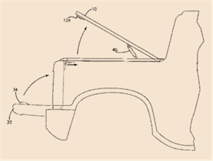
mechanism - An automobile hatchback lift mechanism
- An electric can opener
- A folding ironing board
- A folding card able
- A folding beach chair
- A baby swing
- A folding baby walker
- A fancy corkscrew as shown in Figure P2-9
- A windshield wiper mechanism
- A dump truck dump mechanism
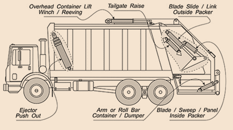
- A trash truck dumpster mechanism
- A pickup truck tailgate mechanism
- An automobile jack
- A collapsible auto radio antenna
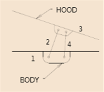
a.
To find:Kinematic diagrams and total DOF in an automobile hood hinge mechanism.
Explanation of Solution
Given information:
The initial conditions that are given are that of an automobile hood hinge mechanism
Calculation:
Here KutzbatchEquation is used to compute mobility (DOF) of the shown system below. An automobile mechanism systemcondition is as shown.
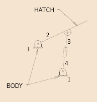
b.
To find:Kinematic diagrams and total DOF inan automobile hatchback lift mechanism.
Explanation of Solution
Given information:
The initial conditions that are given are that of An automobile hatchback lift mechanism.
Calculation:
Here Kutzbatch Equation is used to compute mobility (DOF) the models below. Here mainly considering the given mechanism of an automobile hatchback lift mechanism which having the

c.
To find:Kinematic diagrams and total DOF in the electric can opener.
Explanation of Solution
Given information:
The initial conditions that are given are that of electric opener has 2 DOF.
Calculation:
Here Kutzbatch Equation is used to compute mobility (DOF) the given mechanismbelow. Here mainly considering the given mechanism of an electric opener has 2 DOF
d.
To find:Kinematic diagrams and total DOF in a folding ironing board.
Explanation of Solution
Given information:
The initial conditions that are given are that of a folding ironing board
Calculation:
Here Kutzbatch Equation is used to compute mobility (DOF) the given mechanism below.Here mainly considering the given mechanism A folding ironing board with One leg joins pivot joint on board and the other is slider joint.
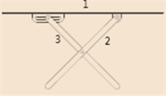
e.
To find:Kinematic diagrams and total DOF in a folding card table.
Explanation of Solution
Given information:
The initial conditions that are given are that ofa folding card table.
Calculation:
Here Kutzbatch Equation is used to compute mobility (DOF) the given mechanism below. A folding card table having 7 DOF for considering 1 for individual leg, 2 for x-ylocation and one for angular orientation.
f.
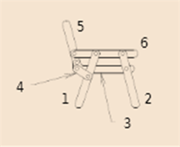
To find:Kinematic diagrams and total DOF in a folding beach chair.
Explanation of Solution
Given information:
The initial conditions that are given are that of a folding beach chair.
Calculation:
Here Kutzbatch Equation is used to compute mobility (DOF) the given mechanism below. A folding beach chair with ternary links having analysis below is Subtract 1 DOF forced stop.
g.
To find:Kinematic diagrams and total DOF in a baby swing.
Explanation of Solution
Given information:
The initial conditions that are given are that ofa baby swing.
Calculation:
Here Kutzbatch Equation is used to compute mobility (DOF) the given mechanism below. A baby swing has 4 DOF,for swing 1 angular orientation w.r.t. frame, and 3 for location and orientation of the frame w.r.t. a 2-D frame.
h.
To find:Kinematic diagrams and total DOF in a folding baby walker.
Explanation of Solution
Given information:
The initial conditions that are given are that ofA folding baby walker
Calculation:
Here Kutzbatch Equation is used to compute mobility (DOF) the given mechanism below. A folding baby walker having 4 DOF with considering of 1 degree with unfolded, and 3 for the walkerlocation and orientation w.r.t.a 2-D frame.
i.
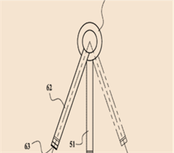
To find:Kinematic diagrams and total DOF in a fancy corkscrew.
Explanation of Solution
Given information:
The initial conditions that are given are that ofa fancy corkscrew.
Calculation:
Here Kutzbatch Equation is used to compute mobility (DOF) the given mechanism below. A fancy corkscrew having 2 DOF for screw rotated and arms rotate to translate w.r.t. screw.
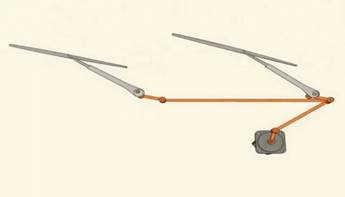
j.
To find:Kinematic diagrams and total DOF in a windshield wiper mechanism.
Explanation of Solution
Given information:
The initial conditions that are given are that of A windshield wiper mechanism.
Calculation:
Here Kutzbatch Equation is used to compute mobility (DOF) the given mechanism below.A windshield wiper mechanism has 1 DOF with considering of the wiper blades position w.r.t. a single input.
k.
To find:Kinematic diagrams and total DOF in a dump truck mechanism.
Explanation of Solution
Given information:
The initial conditions that are given are that of. A dump-truck dump mechanism
Calculation:
Here Kutzbatch Equation is used to compute mobility (DOF) the given mechanism below.A dump-truck dump mechanism having 1 DOF for a angle of dump body for length of the hydraulic cylinder links w.r.t. the body truck.

l.
To find:Kinematic diagrams and total DOF in a trash truck mechanism.
Explanation of Solution
Given information:
The initial conditions that are given are that ofA trash truck dumpster mechanism
Calculation:
Here Kutzbatch Equation is used to compute mobility (DOF) the given mechanism below. A trash truck dumpster mechanism having 2 DOF for generally a rotation and a translation.
m.
To find:Kinematic diagrams and to find their total DOF in a trash truck tailgate mechanism.
Explanation of Solution
Given information:
The initial conditions that are given are that ofa pickup tailgate mechanism.
Calculation:
Here Kutzbatch Equation is used to compute mobility (DOF) the given mechanism below. A pickup tailgate mechanism having a 1 DOF.
n.
To find:Kinematic diagrams and total DOF in an automobile jack.
Explanation of Solution
Given information:
The initial conditions that are given are that ofAn automobile jack mechanism.
Calculation:
Here Kutzbatch Equation is used to compute mobility (DOF) the given mechanism below. An automobile jack having 1 DOF for height jack and the other for the positionand orientation of the jack w.r.t. a 2-D frame.
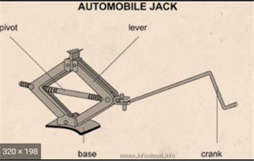
, total4 DOF
o.
To find:Kinematic diagrams and total DOF in a collapsible auto radio antenna.
Explanation of Solution
Given information:
The initial conditions that are given are that ofa collapsible auto radio antenna mechanism.
Calculation:
Here Kutzbatch Equation is used to compute mobility (DOF) the given mechanism below. Amany DOF with considering section for a collapsible auto radio antenna, its less one.
Want to see more full solutions like this?
Chapter 2 Solutions
DESIGN OF MACHINERY


- (Read image) (Answer given)arrow_forwardProblem (17): water flowing in an open channel of a rectangular cross-section with width (b) transitions from a mild slope to a steep slope (i.e., from subcritical to supercritical flow) with normal water depths of (y₁) and (y2), respectively. Given the values of y₁ [m], y₂ [m], and b [m], calculate the discharge in the channel (Q) in [Lit/s]. Givens: y1 = 4.112 m y2 = 0.387 m b = 0.942 m Answers: ( 1 ) 1880.186 lit/s ( 2 ) 4042.945 lit/s ( 3 ) 2553.11 lit/s ( 4 ) 3130.448 lit/sarrow_forwardProblem (14): A pump is being used to lift water from an underground tank through a pipe of diameter (d) at discharge (Q). The total head loss until the pump entrance can be calculated as (h₁ = K[V²/2g]), h where (V) is the flow velocity in the pipe. The elevation difference between the pump and tank surface is (h). Given the values of h [cm], d [cm], and K [-], calculate the maximum discharge Q [Lit/s] beyond which cavitation would take place at the pump entrance. Assume Turbulent flow conditions. Givens: h = 120.31 cm d = 14.455 cm K = 8.976 Q Answers: (1) 94.917 lit/s (2) 49.048 lit/s ( 3 ) 80.722 lit/s 68.588 lit/s 4arrow_forward
- Problem (13): A pump is being used to lift water from the bottom tank to the top tank in a galvanized iron pipe at a discharge (Q). The length and diameter of the pipe section from the bottom tank to the pump are (L₁) and (d₁), respectively. The length and diameter of the pipe section from the pump to the top tank are (L2) and (d2), respectively. Given the values of Q [L/s], L₁ [m], d₁ [m], L₂ [m], d₂ [m], calculate total head loss due to friction (i.e., major loss) in the pipe (hmajor-loss) in [cm]. Givens: L₁,d₁ Pump L₂,d2 오 0.533 lit/s L1 = 6920.729 m d1 = 1.065 m L2 = 70.946 m d2 0.072 m Answers: (1) 3.069 cm (2) 3.914 cm ( 3 ) 2.519 cm ( 4 ) 1.855 cm TABLE 8.1 Equivalent Roughness for New Pipes Pipe Riveted steel Concrete Wood stave Cast iron Galvanized iron Equivalent Roughness, & Feet Millimeters 0.003-0.03 0.9-9.0 0.001-0.01 0.3-3.0 0.0006-0.003 0.18-0.9 0.00085 0.26 0.0005 0.15 0.045 0.000005 0.0015 0.0 (smooth) 0.0 (smooth) Commercial steel or wrought iron 0.00015 Drawn…arrow_forwardThe flow rate is 12.275 Liters/s and the diameter is 6.266 cm.arrow_forwardAn experimental setup is being built to study the flow in a large water main (i.e., a large pipe). The water main is expected to convey a discharge (Qp). The experimental tube will be built at a length scale of 1/20 of the actual water main. After building the experimental setup, the pressure drop per unit length in the model tube (APm/Lm) is measured. Problem (20): Given the value of APm/Lm [kPa/m], and assuming pressure coefficient similitude, calculate the drop in the pressure per unit length of the water main (APP/Lp) in [Pa/m]. Givens: AP M/L m = 590.637 kPa/m meen Answers: ( 1 ) 59.369 Pa/m ( 2 ) 73.83 Pa/m (3) 95.443 Pa/m ( 4 ) 44.444 Pa/m *******arrow_forward
- Find the reaction force in y if Ain = 0.169 m^2, Aout = 0.143 m^2, p_in = 0.552 atm, Q = 0.367 m^3/s, α = 31.72 degrees. The pipe is flat on the ground so do not factor in weight of the pipe and fluid.arrow_forwardFind the reaction force in x if Ain = 0.301 m^2, Aout = 0.177 m^2, p_in = 1.338 atm, Q = 0.669 m^3/s, and α = 37.183 degreesarrow_forwardProblem 5: Three-Force Equilibrium A structural connection at point O is in equilibrium under the action of three forces. • • . Member A applies a force of 9 kN vertically upward along the y-axis. Member B applies an unknown force F at the angle shown. Member C applies an unknown force T along its length at an angle shown. Determine the magnitudes of forces F and T required for equilibrium, assuming 0 = 90° y 9 kN Aarrow_forward
- Problem 19: Determine the force in members HG, HE, and DE of the truss, and state if the members are in tension or compression. 4 ft K J I H G B C D E F -3 ft -3 ft 3 ft 3 ft 3 ft- 1500 lb 1500 lb 1500 lb 1500 lb 1500 lbarrow_forwardProblem 14: Determine the reactions at the pin A, and the tension in cord. Neglect the thickness of the beam. F1=26kN F2 13 12 80° -2m 3marrow_forwardProblem 22: Determine the force in members GF, FC, and CD of the bridge truss and state if the members are in tension or compression. F 15 ft B D -40 ft 40 ft -40 ft 40 ft- 5 k 10 k 15 k 30 ft Earrow_forward
 Elements Of ElectromagneticsMechanical EngineeringISBN:9780190698614Author:Sadiku, Matthew N. O.Publisher:Oxford University Press
 Mechanics of Materials (10th Edition)Mechanical EngineeringISBN:9780134319650Author:Russell C. HibbelerPublisher:PEARSON
 Thermodynamics: An Engineering ApproachMechanical EngineeringISBN:9781259822674Author:Yunus A. Cengel Dr., Michael A. BolesPublisher:McGraw-Hill Education
 Control Systems EngineeringMechanical EngineeringISBN:9781118170519Author:Norman S. NisePublisher:WILEY
 Mechanics of Materials (MindTap Course List)Mechanical EngineeringISBN:9781337093347Author:Barry J. Goodno, James M. GerePublisher:Cengage Learning
 Engineering Mechanics: StaticsMechanical EngineeringISBN:9781118807330Author:James L. Meriam, L. G. Kraige, J. N. BoltonPublisher:WILEY