
DESIGN OF MACHINERY
6th Edition
ISBN: 9781260113310
Author: Norton
Publisher: RENT MCG
expand_more
expand_more
format_list_bulleted
Concept explainers
Videos
Textbook Question
Chapter 2, Problem 2.64P
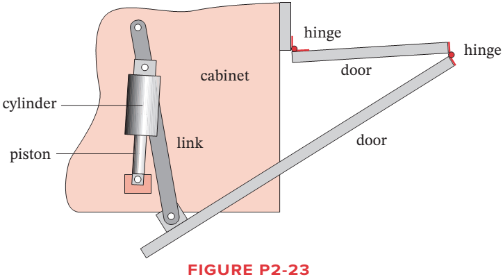
Figure P2-23 shows the top view of the partially open doors on one side of an entertainment center cabinet. The wooden doors are hinged to each other and one door is hinged to the cabinet. There is also a ternary, metal link attached to the cabinet and
Expert Solution & Answer
Want to see the full answer?
Check out a sample textbook solution
Students have asked these similar questions
using the theorem of three moments, find all the moments, I need concise calculations only
Practise question need help on
Can you show explaination and working. The answer from the text book is Q=5.03 X 10^-3
Chapter 2 Solutions
DESIGN OF MACHINERY
Ch. 2 - Find three (or other number as assigned) of the...Ch. 2 - How many DOF do you have in your wrist and hand...Ch. 2 - How many DOF do the following joints have? Your...Ch. 2 - How many DOF do the following have in their normal...Ch. 2 - Are the joints in Problem 2-3 force closed or form...Ch. 2 - Describe the motion of the following items as pure...Ch. 2 - Calculate the mobility of the linkages assigned...Ch. 2 - Identify the items in Figure P2-1 as mechanisms,...Ch. 2 - Use linkage transformation on the linkage of...Ch. 2 - Prob. 2.10P
Ch. 2 - Use number synthesis to find all the possible link...Ch. 2 - Prob. 2.12PCh. 2 - Use linkage transformation to create a 1-DOF...Ch. 2 - Use linkage transformation to create a 1-DOF...Ch. 2 - Calculate the Grashof condition of the fourbar...Ch. 2 - Prob. 2.16PCh. 2 - Describe the difference between a cam-follower...Ch. 2 - Examine an automobile hood hinge mechanism of the...Ch. 2 - Find an adjustable arm desk lamp of the type shown...Ch. 2 - The torque-speed curve for a 1/8 hp permanent...Ch. 2 - Find the mobility of the mechanisms in Figure...Ch. 2 - Find the Grashof condition and Barker...Ch. 2 - Find the rotatability of each loop of the...Ch. 2 - Find the mobility of the mechanisms in Figure...Ch. 2 - Find the mobility of the ice tongs in Figure P2-6:...Ch. 2 - Prob. 2.26PCh. 2 - Prob. 2.27PCh. 2 - Find the mobility of the corkscrew in Figure P2-9.Ch. 2 - Figure P2-10 shows Watts sun and planet drive that...Ch. 2 - Figure P2-11 shows a bicycle handbrake lever...Ch. 2 - Figure P2-12 shows a bicycle brake caliper...Ch. 2 - Find the mobility, the Grashof condition, and the...Ch. 2 - The approximate torque-speed curve and its...Ch. 2 - Prob. 2.34PCh. 2 - Prob. 2.35PCh. 2 - Sketch the equivalent linkage for the cam and...Ch. 2 - Describe the motion of the following rides,...Ch. 2 - For the mechanism in Figure P2-1 a, number the...Ch. 2 - Repeat Problem 2-38 for Figure P2-1b.Ch. 2 - Repeat Problem 2-38 for Figure P2-1c.Ch. 2 - Prob. 2.41PCh. 2 - Find the mobility, the Grashof condition, and the...Ch. 2 - Find the mobility, the Grashof condition, and the...Ch. 2 - Figure P2-20 shows a Rube Goldberg mechanism that...Ch. 2 - All the eightbar linkages in Figure 2-11 part 2...Ch. 2 - Prob. 2.46PCh. 2 - Prob. 2.47PCh. 2 - Find the mobility of the mechanism shown in Figure...Ch. 2 - Find the mobility of the mechanism shown in Figure...Ch. 2 - Find the mobility of the mechanism shown in Figure...Ch. 2 - Find the mobility of the mechanism shown in Figure...Ch. 2 - Prob. 2.52PCh. 2 - Prob. 2.53PCh. 2 - Repeat Problem 2-38 for Figure P2-1f.Ch. 2 - Repeat Problem 2-38 for Figure P2-1g.Ch. 2 - For the example linkage shown in Figure 2-4 find...Ch. 2 - For the linkage shown in Figure 2-5b find the...Ch. 2 - Prob. 2.58PCh. 2 - Figure P2-21b shows a mechanism. Find its mobility...Ch. 2 - Prob. 2.60PCh. 2 - Figure P2-21 d shows a log transporter. Draw a...Ch. 2 - Figure P2-21e shows a plow mechanism attached to a...Ch. 2 - Figure P2-22 shows a Hart inversor sixbar linkage....Ch. 2 - Figure P2-23 shows the top view of the partially...Ch. 2 - Figure P2-24a shows the seat and seat-back of a...Ch. 2 - Figure P2-24b shows the mechanism used to extend...Ch. 2 - Figure P2-24b shows the mechanism used to extend...Ch. 2 - Figure P2-25 shows a sixbar linkage. Is it a Watt...Ch. 2 - Use number synthesis o find all the possible link...Ch. 2 - Use number synthesis to find all the possible link...Ch. 2 - Prob. 2.71PCh. 2 - For the mechanism in Figure P2-26, number the...Ch. 2 - Figure P2-27 shows a schematic of an exercise...Ch. 2 - Calculate the mobility of the linkage in Figure...Ch. 2 - Calculate the Grashof condition of the fourbar...Ch. 2 - The drum brake mechanism in Figure P2-4g is a...
Knowledge Booster


Learn more about
Need a deep-dive on the concept behind this application? Look no further. Learn more about this topic, mechanical-engineering and related others by exploring similar questions and additional content below.Similar questions
- practise questionarrow_forwardCan you provide steps and an explaination on how the height value to calculate the Pressure at point B is (-5-3.5) and the solution is 86.4kPa.arrow_forwardPROBLEM 3.46 The solid cylindrical rod BC of length L = 600 mm is attached to the rigid lever AB of length a = 380 mm and to the support at C. When a 500 N force P is applied at A, design specifications require that the displacement of A not exceed 25 mm when a 500 N force P is applied at A For the material indicated determine the required diameter of the rod. Aluminium: Tall = 65 MPa, G = 27 GPa. Aarrow_forward
- Find the equivalent mass of the rocker arm assembly with respect to the x coordinate. k₁ mi m2 k₁arrow_forward2. Figure below shows a U-tube manometer open at both ends and containing a column of liquid mercury of length l and specific weight y. Considering a small displacement x of the manometer meniscus from its equilibrium position (or datum), determine the equivalent spring constant associated with the restoring force. Datum Area, Aarrow_forward1. The consequences of a head-on collision of two automobiles can be studied by considering the impact of the automobile on a barrier, as shown in figure below. Construct a mathematical model (i.e., draw the diagram) by considering the masses of the automobile body, engine, transmission, and suspension and the elasticity of the bumpers, radiator, sheet metal body, driveline, and engine mounts.arrow_forward
- 3.) 15.40 – Collar B moves up at constant velocity vB = 1.5 m/s. Rod AB has length = 1.2 m. The incline is at angle = 25°. Compute an expression for the angular velocity of rod AB, ė and the velocity of end A of the rod (✓✓) as a function of v₂,1,0,0. Then compute numerical answers for ȧ & y_ with 0 = 50°.arrow_forward2.) 15.12 The assembly shown consists of the straight rod ABC which passes through and is welded to the grectangular plate DEFH. The assembly rotates about the axis AC with a constant angular velocity of 9 rad/s. Knowing that the motion when viewed from C is counterclockwise, determine the velocity and acceleration of corner F.arrow_forward500 Q3: The attachment shown in Fig.3 is made of 1040 HR. The static force is 30 kN. Specify the weldment (give the pattern, electrode number, type of weld, length of weld, and leg size). Fig. 3 All dimension in mm 30 kN 100 (10 Marks)arrow_forward
- (read image) (answer given)arrow_forwardA cylinder and a disk are used as pulleys, as shown in the figure. Using the data given in the figure, if a body of mass m = 3 kg is released from rest after falling a height h 1.5 m, find: a) The velocity of the body. b) The angular velocity of the disk. c) The number of revolutions the cylinder has made. T₁ F Rd = 0.2 m md = 2 kg T T₂1 Rc = 0.4 m mc = 5 kg ☐ m = 3 kgarrow_forward(read image) (answer given)arrow_forward
arrow_back_ios
SEE MORE QUESTIONS
arrow_forward_ios
Recommended textbooks for you
 Principles of Heat Transfer (Activate Learning wi...Mechanical EngineeringISBN:9781305387102Author:Kreith, Frank; Manglik, Raj M.Publisher:Cengage Learning
Principles of Heat Transfer (Activate Learning wi...
Mechanical Engineering
ISBN:9781305387102
Author:Kreith, Frank; Manglik, Raj M.
Publisher:Cengage Learning
Force | Free Body Diagrams | Physics | Don't Memorise; Author: Don't Memorise;https://www.youtube.com/watch?v=4Bwwq1munB0;License: Standard YouTube License, CC-BY