
Applied Fluid Mechanics
7th Edition
ISBN: 9780133414622
Author: UNTENER
Publisher: YUZU
expand_more
expand_more
format_list_bulleted
Videos
Textbook Question
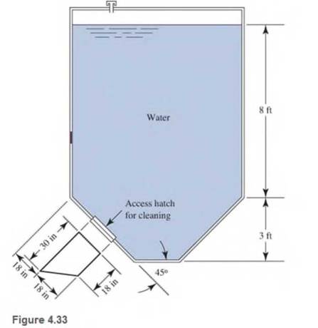
Chapter 4, Problem 4.21PP
Refer to Fig 4.33
Expert Solution & Answer
Want to see the full answer?
Check out a sample textbook solution
Students have asked these similar questions
Explained step by step.
The bevel gear shown in is subjected to the force F which is caused
from contact with another gear.
Part A
F (201+8j 15k) N
40 mm
Determine the moment of this force about the y axis of the gear shaft.
Express your answer with the appropriate units.
My =
Value
Submit
Request Answer
?
Units
30 mm
Consider the beam in.
Part A
1.5 ft
200 lb
200lb
2 ft
30°
1.25 ft
30°
If F 90 lb, determine the resultant couple moment.
=
Express your answer in pound-feet to three significant figures. Assume the positive direction is counterclockwise.
ΑΣΦ
vec
MR =
Submit
Request Answer
?
lb.ft
Chapter 4 Solutions
Applied Fluid Mechanics
Ch. 4 - figure 4.2 shows a vacuum tank with a flat...Ch. 4 - The flat left end of the tank shown in Fig. 4.21...Ch. 4 - An exhaust system for a room creates a partial...Ch. 4 - A piece of 14 -in Schedule 40 pipe is used as a...Ch. 4 - A pressure relief valve is designed so that the...Ch. 4 - A gas-powered cannon shoots projectiles by...Ch. 4 - The egress hatch of a manned spacecraft is...Ch. 4 - A tank containing liquid ammonia at 77F has a flat...Ch. 4 - The bottom of a laboratory vat has a hole in it to...Ch. 4 - A simple shower for remote locations is designed...
Ch. 4 - Calculate the total force on the bottom of the...Ch. 4 - If the length of the tank in Fig. 4.24 is 1.2m,...Ch. 4 - An observation port in a small submarine is...Ch. 4 - A rectangular gate is installed in a vertical wall...Ch. 4 - '4.15 A vat has a sloped side, as shown in Fig....Ch. 4 - The wall shown in Fig. 4.28 is 20 ft long, (a)...Ch. 4 - If the wall in Fig. 4.29 is 4m long, calculate the...Ch. 4 - Refer to Fig. 4.30Ch. 4 - Refer to Fig. 4.31Ch. 4 - Refer to Fig.4.32Ch. 4 - Refer to Fig 4.33Ch. 4 - Refer to Fig. 4.34Ch. 4 - Refer to Fig. 4.35 (?Ch. 4 - Swimming poo!WilierGlasswindow2 ft diameterFigure...Ch. 4 - 4.25 Refer to Fig 4.37Ch. 4 - Refer to Fig.4.38Ch. 4 - Refer to Fig.4.39Ch. 4 - Refer to Fig.4.40Ch. 4 - Refer to Fig 4.41Ch. 4 - figure 4.42i5 shows a gasoline tank filled into...Ch. 4 - If the tank in Fig. 4.42 is filled just to the...Ch. 4 - If the tank in Fig. 4.42 is only half full of...Ch. 4 - For the water tank shown in Fig. 4.43, compute the...Ch. 4 - For the water tank shown in Fig. 4.43, compute the...Ch. 4 - For the water tank shown in Fig. 4.43, compute the...Ch. 4 - For the orange-drink tank shown in Fig. 4.32,...Ch. 4 - For the orange-drink tank shown in Fig. 4.32,...Ch. 4 - For the oil tank shown in Fig. 4.35, compute the...Ch. 4 - For the oil tank shown in Fig. 4.35; compute the...Ch. 4 - figure 4.44 shows a rectangular gate holding water...Ch. 4 - figure 4.45 shows a gate hinged at its bottom and...Ch. 4 - figure 4.46 shows a tank of water with a circular...Ch. 4 - Repeat Problem 4.19(Fig. 4.31), except that the...Ch. 4 - Repeat Problem 4.22 (Fig. 4.32), except that the...Ch. 4 - Repeat Problem 4.26 (Fig. 4.38 ). except that the...Ch. 4 - Repeat Problem 4.28 (Fig. 4.40 ), except that the...Ch. 4 - Use Fig 4.47. The surface is 2.00m long.Ch. 4 - Use Fig.4.48. The surface is 2.50m long.Ch. 4 - Use Fig.4.49. The surface is 5.00 ft longCh. 4 - Use Fig.4.50. The surface is 4.50 ft long.Ch. 4 - Use Fig.4.51.The surface is 4.00 m long.Ch. 4 - Use Fig .4.52. The surface is 1.50m longCh. 4 - Use Fig. 4.53. The surface is 1.50m long.Ch. 4 - Use Fig. 4.54. The surface is 60 in longCh. 4 - Repeat Problem 4.47 using Fig. 4.47, except that...Ch. 4 - Repeat Problem 4.48 using Fig. 4.48, except that...Ch. 4 - The tank in Fig. 4.55 has a view port in the...Ch. 4 - Insulated concrete forms (ICFs) are becoming more...Ch. 4 - Lacks are installed in rivers to allow boats to...Ch. 4 - When a dam is installed in a river that has...Ch. 4 - A wealthy eccentric is interested in having an...Ch. 4 - A pneumatic cylinder like the one shown in Fig....Ch. 4 - Determine the magnitude and the location of the...Ch. 4 - For the hinged gate shown in Fig. 4.61, determine...Ch. 4 - Prob. 4.65PPCh. 4 - Write a program to solve Problem 4.41 with any...Ch. 4 - Write a program to solve Problem 4.42 (Fig. 4.46)...Ch. 4 - Write a program to solve curved surface problems...Ch. 4 - For Program 1, cause the depth h to vary over some...
Additional Engineering Textbook Solutions
Find more solutions based on key concepts
1.2 Explain the difference between geodetic and plane
surveys,
Elementary Surveying: An Introduction To Geomatics (15th Edition)
Why is the study of database technology important?
Database Concepts (8th Edition)
Assume a telephone signal travels through a cable at two-thirds the speed of light. How long does it take the s...
Electric Circuits. (11th Edition)
17–1C A high-speed aircraft is cruising in still air. How does the temperature of air at the nose of the aircra...
Thermodynamics: An Engineering Approach
The following C++ program will not compile because the lines have been mixed up. cout Success\n; cout Success...
Starting Out with C++ from Control Structures to Objects (9th Edition)
The solid steel shaft AC has a diameter of 25 mm and is supported by smooth bearings at D and E. It is coupled ...
Mechanics of Materials (10th Edition)
Knowledge Booster


Learn more about
Need a deep-dive on the concept behind this application? Look no further. Learn more about this topic, mechanical-engineering and related others by exploring similar questions and additional content below.Similar questions
- 4. An operating parameter often used by power plant engineers is the heat rate. The heat rate is defined as, HR Qbioler Wnet where Qbioler is the heat transfer rate (Btu/h) to the water in the boiler due to the combustion of a fuel and Wnet is the net power (kW) delivered by the plant. In comparison, the thermal efficiency of the power plant is defined as, nth Wnet Qbioler where the numerator and denominator have the same units. Consider a power plant that is delivering 1000 MW of power while utilizing a heat transfer rate of 3570 MW at the boiler. Determine the heat rate and thermal efficiency of this power plant.arrow_forwardThe shaft shown in the sketch is subjected to tensile torsional and bending loads Determine the principal stresses at the location of stress concentration ✓ D=45MR F=3MM 1000-M 1000N チ d=30mm 500N 150 мм MM- 120 MA-arrow_forwardcalculate moment of inertia of this tapered beam structurearrow_forward
- The system shown below is in statics equilibrium. Cable OB lies in the xy plane and makes a 30° angle with the positive x-axis. Cable OA lies along the negative y-axis. If the weight of the load being supported is 100 lb, determine the magnitude of the forces in all four cables: OA, OB, OC, and OD.arrow_forwardThis is a mechanics/statics problem involving finding internal reactions, V(x) and M(x). Please refer to image for details. I'm not sure about where to take cuts and how to formulate the equations as a function of x. For my support Reactions I got Ay = 1008.33 lb, By = 1416.67 lb and Cy = 175 lb. and for the first cut V(x) = 1008.33 -250(x) and M(x) = 1008.33x - 125x^2. I'm struggling with the equations for the 2nd and 3rd cut.arrow_forwardAs shown in the figure below, a ring is used to suspend a load and is supported by Cable OA and Spring OB. Given that the tension in Cable OA is 400 N, what is the weight of the load being supported? Assume the system is in static equilibrium.arrow_forward
- 4. (a) State the conditions that must be met to ensure dynamic balance is achieved for long rotors. (b) A rotor carries three out-of-balance discs in planes A, B and C as shown in Figure 4. The out-of- balance mass x radius products of the rotor discs are tabulated in Table 4. The shaft is to be dynamically balanced by adding balancing masses in planes P and Q, spaced along the shaft at a distance da = 800 mm. Determine the magnitude mara and angular position of the balancing mass x radius product that must be added to plane Q. MBB Ов θε mdc Мага End View on Plane P P MBB MATA dA dB dc do Figure 4 moc Table 4 MATA = 0.6 kg mm 6A = 0° d₁ = 200 mm mers = 0.2 kg mm 6g = 45° dB = 400 mm mcrc = 0.4 kg mm Bc=240° dc = 600 mm Ans. (b) = 110.5°, moro = 0.2 kg mmarrow_forwardNeed help in adding demensioning am am so confusedarrow_forwardComplete the following activity. Save as .pdf and upload to the assignment to the dropbox. 口 Use the general dimensioning symbols to correctly specify the following requirements on the drawing above.arrow_forward
- please solve and show workarrow_forwardWater is boiling in a 25 cm diameter aluminum pan (k=237 W/mK) at 95 degrees C. Heat is transferred steadily to the boiling water in the pan through its .5 cm thick flat bottom at a rate of 800 W. if the inner surface temp of the bottom of the pan is 108 degrees C determine the boiling heat transfer coefficent on the inner surface of the pan and the outer surface temp of the bottom of the pan.arrow_forwardplease solve and show workarrow_forward
arrow_back_ios
SEE MORE QUESTIONS
arrow_forward_ios
Recommended textbooks for you
 Elements Of ElectromagneticsMechanical EngineeringISBN:9780190698614Author:Sadiku, Matthew N. O.Publisher:Oxford University Press
 Mechanics of Materials (10th Edition)Mechanical EngineeringISBN:9780134319650Author:Russell C. HibbelerPublisher:PEARSON
 Thermodynamics: An Engineering ApproachMechanical EngineeringISBN:9781259822674Author:Yunus A. Cengel Dr., Michael A. BolesPublisher:McGraw-Hill Education
 Control Systems EngineeringMechanical EngineeringISBN:9781118170519Author:Norman S. NisePublisher:WILEY
 Mechanics of Materials (MindTap Course List)Mechanical EngineeringISBN:9781337093347Author:Barry J. Goodno, James M. GerePublisher:Cengage Learning
 Engineering Mechanics: StaticsMechanical EngineeringISBN:9781118807330Author:James L. Meriam, L. G. Kraige, J. N. BoltonPublisher:WILEY
Elements Of Electromagnetics
Mechanical Engineering
ISBN:9780190698614
Author:Sadiku, Matthew N. O.
Publisher:Oxford University Press
Mechanics of Materials (10th Edition)
Mechanical Engineering
ISBN:9780134319650
Author:Russell C. Hibbeler
Publisher:PEARSON
Thermodynamics: An Engineering Approach
Mechanical Engineering
ISBN:9781259822674
Author:Yunus A. Cengel Dr., Michael A. Boles
Publisher:McGraw-Hill Education
Control Systems Engineering
Mechanical Engineering
ISBN:9781118170519
Author:Norman S. Nise
Publisher:WILEY
Mechanics of Materials (MindTap Course List)
Mechanical Engineering
ISBN:9781337093347
Author:Barry J. Goodno, James M. Gere
Publisher:Cengage Learning
Engineering Mechanics: Statics
Mechanical Engineering
ISBN:9781118807330
Author:James L. Meriam, L. G. Kraige, J. N. Bolton
Publisher:WILEY
Physics 33 - Fluid Statics (1 of 10) Pressure in a Fluid; Author: Michel van Biezen;https://www.youtube.com/watch?v=mzjlAla3H1Q;License: Standard YouTube License, CC-BY