Applied Fluid Mechanics
7th Edition
ISBN: 9780133414622
Author: UNTENER
Publisher: YUZU
bartleby

Videos

Textbook Question
Book Icon
Chapter 4, Problem 4.1PP

figure 4.2 shows a vacuum tank with a flat circular observation window in one end. If the pressure in the tank is 0.12psia when the barometer reads 30.5in of mercury, calculate the total force on the window.

Expert Solution & Answer
Check Mark
To determine

Total force on the window.

Answer to Problem 4.1PP

The required value of the force is 1672.8lb

Explanation of Solution

Given information:
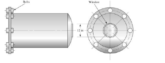
Applied Fluid Mechanics, Chapter 4, Problem 4.1PP

   Pressure (P) = 0.12 psiaPressure head (h) = 30.5 in of hgDiameter (D) = 12 in

Formula used:

   pressure (P) = force(F)area(A)pressure (P) =γhforce (F) = P×A

Calculation:

We know the standard formula to calculate pressure, i.e.: P = force(F)area(A)

Then, F = P×A (a)

   Area (A) = π4(D)2A=π4(12)2A=113.097 in2

Let us assume that the pressure in the tank is Patm=γh

   Patm=(0.4889)(30.5) (specific weight of mercury (γ)=0.4889lb/in3)Patm=14.911lb/in2

Net pressure acting in the tank is, P=PatmPinside;

   P=PatmPinsideP=14.9110.12P=14.791lb/in2

From equation (a);

   F=P×AF=(14.791)(113.097)F=1672.8lb

Then, the net force acting on the window is;

   F=1672.8lb

Want to see more full solutions like this?

Subscribe now to access step-by-step solutions to millions of textbook problems written by subject matter experts!
Students have asked these similar questions
The hoist consists of a single rope and an arrangement of frictionless pulleys as shown. If the angle 0 = 59°, determine the force that must be applied to the rope, Frope, to lift a load of 4.4 kN. The three-pulley and hook assembly at the center of the system has a mass of 22.5 kg with a center of mass that lies on the line of action of the force applied to the hook. e ΘΕ B CC 10 BY NC SA 2013 Michael Swanbom Fhook Note the figure may not be to scale. Frope = KN HO Frope
Determine the tension developed in cables AB and AC and the force developed along strut AD for equilibrium of the 400-lb crate. x. 5.5 ft C 2 ft Z 2 ft D 6 ft B 4 ft A 2.5 ft
A block of mass m hangs from the end of bar AB that is 7.2 meters long and connected to the wall in the xz plane. The bar is supported at A by a ball joint such that it carries only a compressive force along its axis. The bar is supported at end B by cables BD and BC that connect to the xz plane at points C and D respectively with coordinates given in the figure. Cable BD is elastic and can be modeled as a linear spring with a spring constant k = 400 N/m and unstretched length of 6.34 meters. Determine the mass m, the compressive force in beam AB and the tension force in cable BC. Z D (c, 0, d) C (a, 0, b), A e B y f m BY NC SA x 2016 Eric Davishahl Values for dimensions on the figure are given in the following table. Note the figure may not be to scale. Variable Value a 8.1 m b 3.3 m C 2.7 m d 3.9 m e 2 m f 5.4 m The mass of the block is The compressive force in bar AB is The tension in cable S is N. kg.

Chapter 4 Solutions

Applied Fluid Mechanics

Ch. 4 - Calculate the total force on the bottom of the...Ch. 4 - If the length of the tank in Fig. 4.24 is 1.2m,...Ch. 4 - An observation port in a small submarine is...Ch. 4 - A rectangular gate is installed in a vertical wall...Ch. 4 - '4.15 A vat has a sloped side, as shown in Fig....Ch. 4 - The wall shown in Fig. 4.28 is 20 ft long, (a)...Ch. 4 - If the wall in Fig. 4.29 is 4m long, calculate the...Ch. 4 - Refer to Fig. 4.30Ch. 4 - Refer to Fig. 4.31Ch. 4 - Refer to Fig.4.32Ch. 4 - Refer to Fig 4.33Ch. 4 - Refer to Fig. 4.34Ch. 4 - Refer to Fig. 4.35 (?Ch. 4 - Swimming poo!WilierGlasswindow2 ft diameterFigure...Ch. 4 - 4.25 Refer to Fig 4.37Ch. 4 - Refer to Fig.4.38Ch. 4 - Refer to Fig.4.39Ch. 4 - Refer to Fig.4.40Ch. 4 - Refer to Fig 4.41Ch. 4 - figure 4.42i5 shows a gasoline tank filled into...Ch. 4 - If the tank in Fig. 4.42 is filled just to the...Ch. 4 - If the tank in Fig. 4.42 is only half full of...Ch. 4 - For the water tank shown in Fig. 4.43, compute the...Ch. 4 - For the water tank shown in Fig. 4.43, compute the...Ch. 4 - For the water tank shown in Fig. 4.43, compute the...Ch. 4 - For the orange-drink tank shown in Fig. 4.32,...Ch. 4 - For the orange-drink tank shown in Fig. 4.32,...Ch. 4 - For the oil tank shown in Fig. 4.35, compute the...Ch. 4 - For the oil tank shown in Fig. 4.35; compute the...Ch. 4 - figure 4.44 shows a rectangular gate holding water...Ch. 4 - figure 4.45 shows a gate hinged at its bottom and...Ch. 4 - figure 4.46 shows a tank of water with a circular...Ch. 4 - Repeat Problem 4.19(Fig. 4.31), except that the...Ch. 4 - Repeat Problem 4.22 (Fig. 4.32), except that the...Ch. 4 - Repeat Problem 4.26 (Fig. 4.38 ). except that the...Ch. 4 - Repeat Problem 4.28 (Fig. 4.40 ), except that the...Ch. 4 - Use Fig 4.47. The surface is 2.00m long.Ch. 4 - Use Fig.4.48. The surface is 2.50m long.Ch. 4 - Use Fig.4.49. The surface is 5.00 ft longCh. 4 - Use Fig.4.50. The surface is 4.50 ft long.Ch. 4 - Use Fig.4.51.The surface is 4.00 m long.Ch. 4 - Use Fig .4.52. The surface is 1.50m longCh. 4 - Use Fig. 4.53. The surface is 1.50m long.Ch. 4 - Use Fig. 4.54. The surface is 60 in longCh. 4 - Repeat Problem 4.47 using Fig. 4.47, except that...Ch. 4 - Repeat Problem 4.48 using Fig. 4.48, except that...Ch. 4 - The tank in Fig. 4.55 has a view port in the...Ch. 4 - Insulated concrete forms (ICFs) are becoming more...Ch. 4 - Lacks are installed in rivers to allow boats to...Ch. 4 - When a dam is installed in a river that has...Ch. 4 - A wealthy eccentric is interested in having an...Ch. 4 - A pneumatic cylinder like the one shown in Fig....Ch. 4 - Determine the magnitude and the location of the...Ch. 4 - For the hinged gate shown in Fig. 4.61, determine...Ch. 4 - Prob. 4.65PPCh. 4 - Write a program to solve Problem 4.41 with any...Ch. 4 - Write a program to solve Problem 4.42 (Fig. 4.46)...Ch. 4 - Write a program to solve curved surface problems...Ch. 4 - For Program 1, cause the depth h to vary over some...

Additional Engineering Textbook Solutions

Find more solutions based on key concepts
Knowledge Booster
Background pattern image
Mechanical Engineering
Learn more about
Need a deep-dive on the concept behind this application? Look no further. Learn more about this topic, mechanical-engineering and related others by exploring similar questions and additional content below.
Similar questions
SEE MORE QUESTIONS
Recommended textbooks for you
Text book image
International Edition---engineering Mechanics: St...
Mechanical Engineering
ISBN:9781305501607
Author:Andrew Pytel And Jaan Kiusalaas
Publisher:CENGAGE L
Physics 33 - Fluid Statics (1 of 10) Pressure in a Fluid; Author: Michel van Biezen;https://www.youtube.com/watch?v=mzjlAla3H1Q;License: Standard YouTube License, CC-BY