
Applied Statics and Strength of Materials (6th Edition)
6th Edition
ISBN: 9780133840544
Author: George F. Limbrunner, Craig D'Allaird, Leonard Spiegel
Publisher: PEARSON
expand_more
expand_more
format_list_bulleted
Videos
Textbook Question
Chapter 4, Problem 4.13P
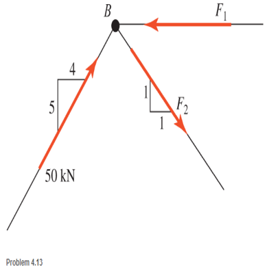
Three members of a truss intersect at joint B as shown. The forces in the members are concurrent at the joint. Force F1 is horizontal. Determine forces F1 and F2.
Expert Solution & Answer

Learn your wayIncludes step-by-step video

schedule06:32
Students have asked these similar questions
Solve for the forces in each of the member. Identify if compression or tension.

The force in member CD of the given truss
The cantilever truss shown is hinged at D and E. Find the forces in each
members.
5 kN
60°
60°
30°
E
3m
6m
5 kN
5 kN
Chapter 4 Solutions
Applied Statics and Strength of Materials (6th Edition)
Ch. 4 - and 4.2 Sketch free-body diagram for the members...Ch. 4 - Sketch free-body diagram for the members shown.Ch. 4 - A steel cylinder having a mass of 120 kgis...Ch. 4 - A 50-lb block is supported by a pin support and a...Ch. 4 - A cylinder weighing 200 lb is supported on an...Ch. 4 - A weight W is supported by a flexible cable and an...Ch. 4 - The ladder shown is supported by a smooth...Ch. 4 - What horizontal force F applied at the center of...Ch. 4 - Calculate the force in cable AB and the angle (...Ch. 4 - Calculate the horizontal force F that should be...
Ch. 4 - Calculate the reactions of the two smooth inclined...Ch. 4 - Calculate the force in each cable for the...Ch. 4 - Three members of a truss intersect at joint B as...Ch. 4 - Four concurrent forces in equilibrium act at point...Ch. 4 - The beam shown carries vertical concentrated...Ch. 4 - Find the reactions at A and B for the beam shown....Ch. 4 - A simply supported beam spans 10 m. The beam...Ch. 4 - The beam shown carries vertical loads. Calculate...Ch. 4 - Calculate the reaction at each support for the...Ch. 4 - Calculate the reactions at A and B for the beam...Ch. 4 - Calculate the reactions at A and B for the beam...Ch. 4 - A 12-ft simple beam is supported at each end. It...Ch. 4 - The beam shown carries vertical loads as...Ch. 4 - Determine the reactions for the beam shown. The...Ch. 4 - Calculate the reaction at each support for the...Ch. 4 - Calculate the wall reactions for the cantilever...Ch. 4 - Determine the reactions at supports A and B of the...Ch. 4 - A mass M of 300 kg is supported by a boom, as...Ch. 4 - Rework Problem 4.28 assuming that point D has been...Ch. 4 - Calculate the force in the tie rod BC and the...Ch. 4 - The davit shown is used in pairs for...Ch. 4 - For the following computer problems, any...Ch. 4 - For the following computer problems, any...Ch. 4 - For the following computer problems, any...Ch. 4 - For the structure shown, draw free-body diagram...Ch. 4 - A 1200-lb load is supported by a cable that runs...Ch. 4 - For the pin-connected frame shown, sketch a...Ch. 4 - For the concurrent force system shown, calculate...Ch. 4 - A strut having a mass of 40 kg/m is supported by a...Ch. 4 - Calculate the reaction at each support for the...Ch. 4 - Calculate the reaction at each support for the...Ch. 4 - A beam supports a nonuniformly distributed load as...Ch. 4 - Calculate the reactions at each support for the...Ch. 4 - Compute reactions at each support for the beam...Ch. 4 - A rod of uniform cross section weighs 4 lb/ft and...Ch. 4 - A 12-ft-long weightiness member supports two...Ch. 4 - A uniform rod AB, having a weight of 5.00 lb and a...Ch. 4 - The plastic barrel tent anchor of Problem 2.11...Ch. 4 - Compute the reactions at A and B for the bracket...Ch. 4 - The truss shown is supported by a pin at A and a...Ch. 4 - Find the reactions at supports A and B for the...Ch. 4 - Find the reactions at supports A and B for the...Ch. 4 - Determine the reactions at A and B for the truss...Ch. 4 - A 40-ft ladder weighing 130 lb is pin-connected to...Ch. 4 - The frame shown is pin-connected at point A and...Ch. 4 - Prob. 4.56SPCh. 4 - A horizontal beam is pin-connected to a wall at...Ch. 4 - Calculate the force in the cable for the structure...Ch. 4 - The Thenard shutter dam shown was originally...Ch. 4 - An inclined railway can be used to lift heavy...Ch. 4 - Two cylinders are supported in a box, as shown....
Additional Engineering Textbook Solutions
Find more solutions based on key concepts
State if the members are in tension or compression. Prob. F6-9
Engineering Mechanics: Statics
Determine the angular velocity of the radial line OA at this instant.
Engineering Mechanics: Dynamics (14th Edition)
ICA 2-1
For each of the following situations, indicate whether you think the action is ethical or unethical or ...
Thinking Like an Engineer: An Active Learning Approach (4th Edition)
Determine the force in members BC, CF, and FE and state if the members are in tension or compression. Prob. F5-...
Statics and Mechanics of Materials (5th Edition)
The magnitude of resultant force FR acting on the screw eye and its direction θ measured clockwise from the x a...
Engineering Mechanics: Statics & Dynamics (14th Edition)
What parts are included in the vehicle chassis?
Automotive Technology: Principles, Diagnosis, and Service (5th Edition)
Knowledge Booster


Learn more about
Need a deep-dive on the concept behind this application? Look no further. Learn more about this topic, mechanical-engineering and related others by exploring similar questions and additional content below.Similar questions
- (A) Draw the components of the load in each member of the frame shown. Assume that BC and AC exert tension and CD exerts compression. Use the symbols Ax, Ay and Az for the x, y and z components respectively of force AC. Follow the same manner of representing the components of the forces in the other members, i.e., Bx, By, Bz and Dx, Dy and Dz accordingly. (B) Set up the equilibrium equation based on summation of moments about AB. Use the symbols indicated in (A). Take the counterclockwise moment as positive. (C) Set up the equilibrium equilibrium equation based on summation of moments about a vertical line passing through A (VA). Use the same symbols as in (A). Take the counterclockwise sense as positive. (D) Determine the load in member BC. Indicate if tension or compression. No need to convert units. express the answer in kips. y 24' 10 A 48' 20 kips Darrow_forwardSolve for the forces in each of the member. Identify if compression or tension.arrow_forward● Determine the force in each member of the truss and state if the members are in tension or compression. 500 lb -3 ft- B 500 lb -3 ft- 9 ft -3 ft- D OE 6 ft 6 ftarrow_forward
- 5. (2 Points) Determine the force in members BE and BD of the loaded truss. The force are positive if in tension, negative if in compression. Assume F₁ = 2660 lb, F₂ = 3050 lb, a = 5.4 ft, b = 8.2 ft, c = 3.0 ft, and d =4.2 ft. F₁ a E barrow_forwardThe Howe bridge truss is subjected to the loading shown. Determine the force in members HI,HB, and BC, and state if the members are in tension or compressionarrow_forwardFind the forces in members CD, DH, and HI.arrow_forward
- The 180-lb homogeneous bar is supported by a ball-and-socket joint at A and two cables attached to B. Determine the forces in the cables.arrow_forwardThe 350-lb homogeneous plate has the shape of an isosceles triangle. The plate is supported by a thrust hinge at A, a slider hinge at B, and the cable CD. Find the force in the cable and the magnitudes of the hinge reactions.arrow_forwardAssuming that P=48000lb and that it may be applied at any joint on the line FJ, determine the location of P that would cause (a) maximum tension in member HI; (b) maximum compression in member CI; and (c) maximum tension in member CI. Also determine the magnitude of the indicated force in each case.arrow_forward
- Determine The Forces In Members AD And DG. The Forces Are Positive If In Tension, Negative If In Compression. Assume h=1.2darrow_forward2. Use the method of sections to determine the forces in members AB, FG, AH, and GH. State whether the forces are in tension or compression. -2.5 m la F 5 kN -2.5 m- E 3 kN -2.5 m O 2 kN 3 marrow_forward3. Determine the force in members BC, CE, and FG of the truss shown using method of section. State whether the members are in tension or compression. 560 lb 560 lb 560 lb A Summary: - 3 ft - B 3 ft- 3 ft – D МЕМBER FORCE (Ib) |2 ft BC E H CE G FG Farrow_forward
arrow_back_ios
SEE MORE QUESTIONS
arrow_forward_ios
Recommended textbooks for you
 International Edition---engineering Mechanics: St...Mechanical EngineeringISBN:9781305501607Author:Andrew Pytel And Jaan KiusalaasPublisher:CENGAGE L
International Edition---engineering Mechanics: St...
Mechanical Engineering
ISBN:9781305501607
Author:Andrew Pytel And Jaan Kiusalaas
Publisher:CENGAGE L
How to balance a see saw using moments example problem; Author: Engineer4Free;https://www.youtube.com/watch?v=d7tX37j-iHU;License: Standard Youtube License