
Applied Statics and Strength of Materials (6th Edition)
6th Edition
ISBN: 9780133840544
Author: George F. Limbrunner, Craig D'Allaird, Leonard Spiegel
Publisher: PEARSON
expand_more
expand_more
format_list_bulleted
Concept explainers
Videos
Textbook Question
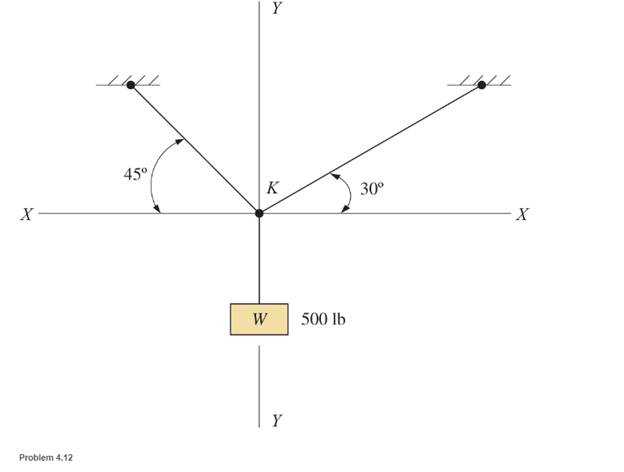
Chapter 4, Problem 4.12P
Calculate the force in each cable for the suspended weight shown.
Expert Solution & Answer

Learn your wayIncludes step-by-step video

schedule03:15
Students have asked these similar questions
using the theorem of three moments, find all the moments, I need concise calculations only
Practise question need help on
Can you show explaination and working. The answer from the text book is Q=5.03 X 10^-3
Chapter 4 Solutions
Applied Statics and Strength of Materials (6th Edition)
Ch. 4 - and 4.2 Sketch free-body diagram for the members...Ch. 4 - Sketch free-body diagram for the members shown.Ch. 4 - A steel cylinder having a mass of 120 kgis...Ch. 4 - A 50-lb block is supported by a pin support and a...Ch. 4 - A cylinder weighing 200 lb is supported on an...Ch. 4 - A weight W is supported by a flexible cable and an...Ch. 4 - The ladder shown is supported by a smooth...Ch. 4 - What horizontal force F applied at the center of...Ch. 4 - Calculate the force in cable AB and the angle (...Ch. 4 - Calculate the horizontal force F that should be...
Ch. 4 - Calculate the reactions of the two smooth inclined...Ch. 4 - Calculate the force in each cable for the...Ch. 4 - Three members of a truss intersect at joint B as...Ch. 4 - Four concurrent forces in equilibrium act at point...Ch. 4 - The beam shown carries vertical concentrated...Ch. 4 - Find the reactions at A and B for the beam shown....Ch. 4 - A simply supported beam spans 10 m. The beam...Ch. 4 - The beam shown carries vertical loads. Calculate...Ch. 4 - Calculate the reaction at each support for the...Ch. 4 - Calculate the reactions at A and B for the beam...Ch. 4 - Calculate the reactions at A and B for the beam...Ch. 4 - A 12-ft simple beam is supported at each end. It...Ch. 4 - The beam shown carries vertical loads as...Ch. 4 - Determine the reactions for the beam shown. The...Ch. 4 - Calculate the reaction at each support for the...Ch. 4 - Calculate the wall reactions for the cantilever...Ch. 4 - Determine the reactions at supports A and B of the...Ch. 4 - A mass M of 300 kg is supported by a boom, as...Ch. 4 - Rework Problem 4.28 assuming that point D has been...Ch. 4 - Calculate the force in the tie rod BC and the...Ch. 4 - The davit shown is used in pairs for...Ch. 4 - For the following computer problems, any...Ch. 4 - For the following computer problems, any...Ch. 4 - For the following computer problems, any...Ch. 4 - For the structure shown, draw free-body diagram...Ch. 4 - A 1200-lb load is supported by a cable that runs...Ch. 4 - For the pin-connected frame shown, sketch a...Ch. 4 - For the concurrent force system shown, calculate...Ch. 4 - A strut having a mass of 40 kg/m is supported by a...Ch. 4 - Calculate the reaction at each support for the...Ch. 4 - Calculate the reaction at each support for the...Ch. 4 - A beam supports a nonuniformly distributed load as...Ch. 4 - Calculate the reactions at each support for the...Ch. 4 - Compute reactions at each support for the beam...Ch. 4 - A rod of uniform cross section weighs 4 lb/ft and...Ch. 4 - A 12-ft-long weightiness member supports two...Ch. 4 - A uniform rod AB, having a weight of 5.00 lb and a...Ch. 4 - The plastic barrel tent anchor of Problem 2.11...Ch. 4 - Compute the reactions at A and B for the bracket...Ch. 4 - The truss shown is supported by a pin at A and a...Ch. 4 - Find the reactions at supports A and B for the...Ch. 4 - Find the reactions at supports A and B for the...Ch. 4 - Determine the reactions at A and B for the truss...Ch. 4 - A 40-ft ladder weighing 130 lb is pin-connected to...Ch. 4 - The frame shown is pin-connected at point A and...Ch. 4 - Prob. 4.56SPCh. 4 - A horizontal beam is pin-connected to a wall at...Ch. 4 - Calculate the force in the cable for the structure...Ch. 4 - The Thenard shutter dam shown was originally...Ch. 4 - An inclined railway can be used to lift heavy...Ch. 4 - Two cylinders are supported in a box, as shown....
Additional Engineering Textbook Solutions
Find more solutions based on key concepts
A file exists on the disk named students txt. The file contains several records, and each record contains two f...
Starting Out with Python (4th Edition)
_____ are characters or symbols that perform operations on one or more operands.
Starting Out With Visual Basic (8th Edition)
A nozzle at A discharges water with an initial velocity of 36 ft/s at an angle with the horizontal. Determine ...
Vector Mechanics For Engineers
Fill in the blanks in each of the following statements: A relation that has no partial functional dependencies ...
Modern Database Management
What is the difference between the public and private parts of a class?
Computer Science: An Overview (13th Edition) (What's New in Computer Science)
Determine the angle between the force and the line AO. Prob. F2-25
INTERNATIONAL EDITION---Engineering Mechanics: Statics, 14th edition (SI unit)
Knowledge Booster


Learn more about
Need a deep-dive on the concept behind this application? Look no further. Learn more about this topic, mechanical-engineering and related others by exploring similar questions and additional content below.Similar questions
- practise questionarrow_forwardCan you provide steps and an explaination on how the height value to calculate the Pressure at point B is (-5-3.5) and the solution is 86.4kPa.arrow_forwardPROBLEM 3.46 The solid cylindrical rod BC of length L = 600 mm is attached to the rigid lever AB of length a = 380 mm and to the support at C. When a 500 N force P is applied at A, design specifications require that the displacement of A not exceed 25 mm when a 500 N force P is applied at A For the material indicated determine the required diameter of the rod. Aluminium: Tall = 65 MPa, G = 27 GPa. Aarrow_forward
- Find the equivalent mass of the rocker arm assembly with respect to the x coordinate. k₁ mi m2 k₁arrow_forward2. Figure below shows a U-tube manometer open at both ends and containing a column of liquid mercury of length l and specific weight y. Considering a small displacement x of the manometer meniscus from its equilibrium position (or datum), determine the equivalent spring constant associated with the restoring force. Datum Area, Aarrow_forward1. The consequences of a head-on collision of two automobiles can be studied by considering the impact of the automobile on a barrier, as shown in figure below. Construct a mathematical model (i.e., draw the diagram) by considering the masses of the automobile body, engine, transmission, and suspension and the elasticity of the bumpers, radiator, sheet metal body, driveline, and engine mounts.arrow_forward
- 3.) 15.40 – Collar B moves up at constant velocity vB = 1.5 m/s. Rod AB has length = 1.2 m. The incline is at angle = 25°. Compute an expression for the angular velocity of rod AB, ė and the velocity of end A of the rod (✓✓) as a function of v₂,1,0,0. Then compute numerical answers for ȧ & y_ with 0 = 50°.arrow_forward2.) 15.12 The assembly shown consists of the straight rod ABC which passes through and is welded to the grectangular plate DEFH. The assembly rotates about the axis AC with a constant angular velocity of 9 rad/s. Knowing that the motion when viewed from C is counterclockwise, determine the velocity and acceleration of corner F.arrow_forward500 Q3: The attachment shown in Fig.3 is made of 1040 HR. The static force is 30 kN. Specify the weldment (give the pattern, electrode number, type of weld, length of weld, and leg size). Fig. 3 All dimension in mm 30 kN 100 (10 Marks)arrow_forward
- (read image) (answer given)arrow_forwardA cylinder and a disk are used as pulleys, as shown in the figure. Using the data given in the figure, if a body of mass m = 3 kg is released from rest after falling a height h 1.5 m, find: a) The velocity of the body. b) The angular velocity of the disk. c) The number of revolutions the cylinder has made. T₁ F Rd = 0.2 m md = 2 kg T T₂1 Rc = 0.4 m mc = 5 kg ☐ m = 3 kgarrow_forward(read image) (answer given)arrow_forward
arrow_back_ios
SEE MORE QUESTIONS
arrow_forward_ios
Recommended textbooks for you
 International Edition---engineering Mechanics: St...Mechanical EngineeringISBN:9781305501607Author:Andrew Pytel And Jaan KiusalaasPublisher:CENGAGE L
International Edition---engineering Mechanics: St...
Mechanical Engineering
ISBN:9781305501607
Author:Andrew Pytel And Jaan Kiusalaas
Publisher:CENGAGE L
Engineering Basics - Statics & Forces in Equilibrium; Author: Solid Solutions - Professional Design Solutions;https://www.youtube.com/watch?v=dQBvQ2hJZFg;License: Standard YouTube License, CC-BY