
Statics and Mechanics of Materials (5th Edition)
5th Edition
ISBN: 9780134382593
Author: Russell C. Hibbeler
Publisher: PEARSON
expand_more
expand_more
format_list_bulleted
Videos
Textbook Question
Chapter 3.9, Problem 37FP
Determine the resultant force and specify where it acts on the beam, measured from A.
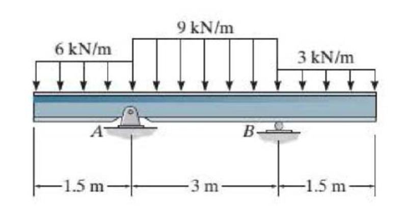
Prob. F3-37
Expert Solution & Answer
Want to see the full answer?
Check out a sample textbook solution
Students have asked these similar questions
Exercises
Find the solution of the following Differential Equations
1) y" + y = 3x²
3)
"+2y+3y=27x
5) y"+y=6sin(x)
7) y"+4y+4y = 18 cosh(x)
9) (4)-5y"+4y = 10 cos(x)
11) y"+y=x²+x
13) y"-2y+y=e*
15) y+2y"-y'-2y=1-4x³
2) y"+2y' + y = x²
4) "+y=-30 sin(4x)
6) y"+4y+3y=sin(x)+2 cos(x)
8) y"-2y+2y= 2e* cos(x)
10) y+y-2y=3e*
12) y"-y=e*
14) y"+y+y=x+4x³ +12x²
16) y"-2y+2y=2e* cos(x)
The state of stress at a point is σ = -4.00 kpsi, σy = 16.00 kpsi, σ = -14.00 kpsi, Try = 11.00 kpsi,
Tyz = 8.000 kpsi, and T = -14.00 kpsi.
Determine the principal stresses.
The principal normal stress σ₁ is determined to be [
The principal normal stress σ2 is determined to be [
The principal normal stress σ3 is determined to be
kpsi.
kpsi.
The principal shear stress 71/2 is determined to be [
The principal shear stress 7½ is determined to be [
The principal shear stress T₁/, is determined to be [
kpsi.
kpsi.
kpsi.
kpsi.
Repeat Problem 28, except using a shaft that is rotatingand transmitting a torque of 150 N * m from the left bearing to the middle of the shaft. Also, there is a profile keyseat at the middle under the load.
(I want to understand this problem)
Chapter 3 Solutions
Statics and Mechanics of Materials (5th Edition)
Ch. 3.4 - In each case, determine the moment of the force...Ch. 3.4 - In each case, set up the determinant to find the...Ch. 3.4 - Determine the moment of the force about point O....Ch. 3.4 - Determine the moment of the force about point O....Ch. 3.4 - Determine the moment of the force about point O....Ch. 3.4 - Determine the moment of the force about point O....Ch. 3.4 - Determine the moment of the force about point O....Ch. 3.4 - Determine the moment of the force about point O....Ch. 3.4 - Determine the resultant moment produced by the...Ch. 3.4 - Determine the resultant moment produced by the...
Ch. 3.4 - Prob. 9FPCh. 3.4 - Prob. 10FPCh. 3.4 - Determine the moment of force F about point O....Ch. 3.4 - If F1 = {100i 120j + 75k} lb and F2 = {200i +...Ch. 3.4 - Prob. 1PCh. 3.4 - Prove the triple scalar product identity A(B C) =...Ch. 3.4 - Given the three nonzero vectors A, B, and C, show...Ch. 3.4 - Determine the moment about point A of each of the...Ch. 3.4 - Determine the moment about point B of each of the...Ch. 3.4 - Prob. 6PCh. 3.4 - Determine the moment of each of the three forces...Ch. 3.4 - Determine the moment of each of the three forces...Ch. 3.4 - Prob. 9PCh. 3.4 - If FB= 30 lb and FC = 45 lb, determine the...Ch. 3.4 - The cable exerts a force of P = 6 kN at the end of...Ch. 3.4 - The cable exerts a force of P = 6 kN at the end of...Ch. 3.4 - Prob. 13PCh. 3.4 - The 20-N horizontal force acts on the handle of...Ch. 3.4 - Two men exert forces of F = 80 lb and P = 50 lb on...Ch. 3.4 - If the man at B exerts a force of P = 30 lb on the...Ch. 3.4 - Prob. 17PCh. 3.4 - Prob. 18PCh. 3.4 - Prob. 19PCh. 3.4 - The handle of the hammer is subjected to the force...Ch. 3.4 - Prob. 21PCh. 3.4 - Prob. 22PCh. 3.4 - The tower crane is used to hoist the 2-Mg load...Ch. 3.4 - The tower crane is used to hoist a 2-Mg load...Ch. 3.4 - Prob. 25PCh. 3.4 - If the 1500-lb boom AB, the 200-lb cage BCD, and...Ch. 3.4 - Prob. 27PCh. 3.4 - Determine the moment of the force F about point P....Ch. 3.4 - The force F = {400i 100j 700k} lb acts at the...Ch. 3.4 - Prob. 30PCh. 3.4 - Determine the moment of the force F about point P....Ch. 3.4 - Prob. 32PCh. 3.4 - A 20-N horizontal force is applied perpendicular...Ch. 3.4 - A 20-N horizontal force is applied perpendicular...Ch. 3.4 - The pipe assembly is subjected to the 80-N force....Ch. 3.4 - The pipe assembly is subjected to the 80-N force....Ch. 3.4 - A force of F = {6i 2j + lk) kN produces a moment...Ch. 3.4 - The force F = {6i + 8j + l0k} N creates a moment...Ch. 3.5 - In each case, determine the resultant moment of...Ch. 3.5 - In each case, set up the determinant needed to...Ch. 3.5 - Determine the magnitude of the moment of the force...Ch. 3.5 - Determine the magnitude of the moment of the force...Ch. 3.5 - Determine the magnitude of the moment of the 200-N...Ch. 3.5 - Determine the magnitude of the moment of the force...Ch. 3.5 - Prob. 17FPCh. 3.5 - Determine the moment of force F about the x, the...Ch. 3.5 - The lug nut on the wheel of the automobile is to...Ch. 3.5 - Prob. 40PCh. 3.5 - The A-frame is being hoisted into an upright...Ch. 3.5 - Prob. 42PCh. 3.5 - Determine the magnitude of the moment of the force...Ch. 3.5 - Determine the moment of force F about an axis...Ch. 3.5 - Prob. 45PCh. 3.5 - The board is used to hold the end of the cross lug...Ch. 3.5 - The A-frame is being hoisted into an upright...Ch. 3.5 - Prob. 48PCh. 3.5 - Prob. 49PCh. 3.5 - Determine the magnitude of the moment of the force...Ch. 3.5 - Prob. 51PCh. 3.5 - Prob. 52PCh. 3.5 - Determine the moment of the force about the aa...Ch. 3.6 - Determine the resultant couple moment acting on...Ch. 3.6 - Determine the resultant couple moment acting on...Ch. 3.6 - Prob. 21FPCh. 3.6 - Prob. 22FPCh. 3.6 - Prob. 23FPCh. 3.6 - Prob. 24FPCh. 3.6 - A clockwise couple M = 5 N m is resisted by the...Ch. 3.6 - A twist of 4 N m is applied to the handle of the...Ch. 3.6 - If the resultant couple of the three couples...Ch. 3.6 - If F = 125 1b, determine the resultant couple...Ch. 3.6 - Determine the magnitude of F so that the resultant...Ch. 3.6 - Determine the magnitude and coordinate direction...Ch. 3.6 - Prob. 60PCh. 3.6 - Prob. 61PCh. 3.6 - Prob. 62PCh. 3.6 - Prob. 63PCh. 3.6 - Express the moment of the couple acting on the...Ch. 3.6 - If the couple moment acting on the pipe has a...Ch. 3.6 - Prob. 66PCh. 3.6 - Prob. 67PCh. 3.6 - Express the moment of the couple acting on the rod...Ch. 3.6 - Prob. 69PCh. 3.6 - Prob. 70PCh. 3.7 - In each case, determine the x and y components of...Ch. 3.7 - Prob. 25FPCh. 3.7 - Replace the loading by an equivalent resultant...Ch. 3.7 - Prob. 27FPCh. 3.7 - Replace the loading by an equivalent resultant...Ch. 3.7 - Prob. 29FPCh. 3.7 - Prob. 30FPCh. 3.7 - Prob. 71PCh. 3.7 - Prob. 72PCh. 3.7 - Prob. 73PCh. 3.7 - Replace the loading acting on the beam by an...Ch. 3.7 - Replace the loading acting on the beam by an...Ch. 3.7 - Prob. 76PCh. 3.7 - Replace the loading acting on the post by an...Ch. 3.7 - Replace the loading acting on the post by a...Ch. 3.7 - Prob. 79PCh. 3.7 - Prob. 80PCh. 3.7 - Prob. 81PCh. 3.7 - Prob. 82PCh. 3.7 - Prob. 83PCh. 3.7 - Replace the force of F = 80 N acting on the pipe...Ch. 3.7 - Prob. 85PCh. 3.7 - The belt passing over the pulley is subjected to...Ch. 3.8 - In each case, determine the x and y components of...Ch. 3.8 - Prob. 7PPCh. 3.8 - Replace the loading by an equivalent resultant...Ch. 3.8 - Prob. 32FPCh. 3.8 - Prob. 33FPCh. 3.8 - Replace the loading by an equivalent resultant...Ch. 3.8 - Replace the loading by an equivalent single...Ch. 3.8 - Prob. 36FPCh. 3.8 - Prob. 87PCh. 3.8 - Prob. 88PCh. 3.8 - Prob. 89PCh. 3.8 - Prob. 90PCh. 3.8 - Replace the loading by a single resultant force....Ch. 3.8 - Replace the loading by a single resultant force....Ch. 3.8 - Replace the loading by a single resultant force....Ch. 3.8 - Prob. 94PCh. 3.8 - Replace the loading on the frame by a single...Ch. 3.8 - Replace the loading acting on the post by a...Ch. 3.8 - Replace the loading acting on the post by a...Ch. 3.8 - Replace the parallel force system acting on the...Ch. 3.8 - Replace the loading acting on the frame by an...Ch. 3.8 - Replace the loading acting on the frame by an...Ch. 3.8 - If FA = 7 kN and FB = 5 kN, represent the force...Ch. 3.8 - Determine the magnitudes of FA and FB so that the...Ch. 3.8 - Prob. 103PCh. 3.8 - The building slab is subjected to four parallel...Ch. 3.8 - The building slab is subjected to four parallel...Ch. 3.8 - If FA = 40 kN and FB = 35 kN, determine the...Ch. 3.8 - If the resultant force is required to act at the...Ch. 3.9 - Determine the resultant force and specify where it...Ch. 3.9 - Prob. 38FPCh. 3.9 - Determine the resultant force and specify where it...Ch. 3.9 - Prob. 40FPCh. 3.9 - Prob. 41FPCh. 3.9 - Prob. 42FPCh. 3.9 - Replace the loading by an equivalent resultant...Ch. 3.9 - Replace the distributed loading with an equivalent...Ch. 3.9 - Replace the loading by an equivalent resultant...Ch. 3.9 - Currently eighty-five percent of all neck injuries...Ch. 3.9 - Prob. 112PCh. 3.9 - Replace the distributed loading by an equivalent...Ch. 3.9 - Replace the distributed loading by an equivalent...Ch. 3.9 - Prob. 115PCh. 3.9 - Determine the equivalent resultant force and...Ch. 3.9 - Determine the magnitude of the equivalent...Ch. 3 - The boom has a length of 30 ft, a weight of 800...Ch. 3 - Replace the force F having a magnitude of F = 50...Ch. 3 - The hood of the automobile is supported by the...Ch. 3 - Prob. 4RPCh. 3 - Prob. 5RPCh. 3 - Prob. 6RPCh. 3 - The building slab is subjected to four parallel...Ch. 3 - Replace the distributed loading by an equivalent...
Knowledge Booster


Learn more about
Need a deep-dive on the concept behind this application? Look no further. Learn more about this topic, mechanical-engineering and related others by exploring similar questions and additional content below.Similar questions
- Prob 2. The material distorts into the dashed position shown. Determine the average normal strains &x, Ey and the shear strain Yxy at A, and the average normal strain along line BE. 50 mm B 200 mm 15 mm 30 mm D ΕΙ 50 mm x A 150 mm Farrow_forwardProb 3. The triangular plate is fixed at its base, and its apex A is given a horizontal displacement of 5 mm. Determine the shear strain, Yxy, at A. Prob 4. The triangular plate is fixed at its base, and its apex A is given a horizontal displacement of 5 mm. Determine the average normal strain & along the x axis. Prob 5. The triangular plate is fixed at its base, and its apex A is given a horizontal displacement of 5 mm. Determine the average normal strain &x along the x' axis. x' 45° 800 mm 45° 45% 800 mm 5 mmarrow_forwardAn airplane lands on the straight runaway, originally travelling at 110 ft/s when s = 0. If it is subjected to the decelerations shown, determine the time t' needed to stop the plane and construct the s -t graph for the motion. draw a graph and show all work step by steparrow_forward
- dny dn-1y dn-1u dn-24 +a1 + + Any = bi +b₂- + +bnu. dtn dtn-1 dtn-1 dtn-2 a) Let be a root of the characteristic equation 1 sn+a1sn- + +an = : 0. Show that if u(t) = 0, the differential equation has the solution y(t) = e\t. b) Let к be a zero of the polynomial b(s) = b₁s-1+b2sn−2+ Show that if the input is u(t) equation that is identically zero. = .. +bn. ekt, then there is a solution to the differentialarrow_forwardB 60 ft WAB AB 30% : The crane's telescopic boom rotates with the angular velocity w = 0.06 rad/s and angular acceleration a = 0.07 rad/s². At the same instant, the boom is extending with a constant speed of 0.8 ft/s, measured relative to the boom. Determine the magnitude of the acceleration of point B at this instant.arrow_forwardThe motion of peg P is constrained by the lemniscate curved slot in OB and by the slotted arm OA. (Figure 1) If OA rotates counterclockwise with a constant angular velocity of 0 = 3 rad/s, determine the magnitude of the velocity of peg P at 0 = 30°. Express your answer to three significant figures and include the appropriate units. Determine the magnitude of the acceleration of peg P at 0 = 30°. Express your answer to three significant figures and include the appropriate units. 0 (4 cos 2 0)m² B Aarrow_forward
- 5: The structure shown was designed to support a30-kN load. It consists of a boom AB with a 30 x 50-mmrectangular cross section and a rod BC with a 20-mm-diametercircular cross section. The boom and the rod are connected bya pin at B and are supported by pins and brackets at A and C,respectively.1. Calculate the normal stress in boom AB and rod BC,indicate if in tension or compression.2. Calculate the shear stress of pins at A, B and C.3. Calculate the bearing stresses at A in member AB,and in the bracket.arrow_forward4: The boom AC is a 4-in. square steel tube with a wallthickness of 0.25 in. The boom is supported by the 0.5-in.-diameter pinat A, and the 0.375-in.-diameter cable BC. The working stresses are 25ksi for the cable, 18 ksi for the boom, and 13.6 ksi for shear in the pin.Neglect the weight of the boom.1. Calculate the maximum value of P (kips) based on boom compression and the maximum value of P (kips) based on tension in the cable.2. Calculate the maximum value of P (kips) based on shear in pin.arrow_forward3: A steel strut S serving as a brace for a boat hoist transmits a compressive force P = 54 kN to the deck of a pier as shown in Fig. STR-08. The strut has a hollow square cross section with a wall thickness t =12mm and the angle θ between the strut and the horizontal is 40°. A pin through the strut transmits the compressive force from the strut to two gusset plates G that are welded to the base plate B. Four anchor bolts fasten the base plate to the deck. The diameter of the pin is 20mm, the thickness of the gusset plates is 16mm, the thickness of the base plate is 8mm, and the diameter of the anchor bolts is 12mm. Disregard any friction between the base plate and the deck.1. Determine the shear stress in the pin, in MPa and the shear stress in the anchor bolts, in MPa.2. Determine the bearing stress in the strut holes, in MPa.arrow_forward
- 1. In the figure, the beam, W410x67, with 9 mm web thicknesssubjects the girder, W530x109 with 12 mm web thickness to a shear load,P (kN). 2L – 90 mm × 90 mm × 6 mm with bolts frame the beam to thegirder.Given: S1 = S2 = S5 = 40 mm; S3 = 75 mm; S4 = 110 mmAllowable Stresses are as follows:Bolt shear stress, Fv = 125 MPaBolt bearing stress, Fp = 510 MPa1. Determine the allowable load, P (kN), based on the shearcapacity of the 4 – 25 mm diameter bolts (4 – d1) and calculate the allowable load, P (kN), based on bolt bearing stress on the web of the beam.2. If P = 450 kN, determine the minimum diameter (mm) of 4 – d1based on allowable bolt shear stress and bearing stress of thebeam web.arrow_forward6: The 6-kN load P is supported by two wooden members of 75 x 125-mm uniform cross section that are joined by the simple glued scarf splice shown.1. Calculate the normal stress in the glue, in MPa.2. Calculate the shear stress in the glue, in MPa.arrow_forwardUsing Matlab calculate the following performance characteristics for a Tesla Model S undergoing the 4506 drive cycle test Prated Trated Ebat 80kW 254 Nm 85kWh/1645kg MUEH A rwheel 0.315M 133.3 C 0.491 Ng ng 7g 8.190.315 8.19 0.315 7ed= 85% Ebpt 35-956 DRIVE AXLE Ebfb chę =85% V Minverter H/A Battery Charger En AC Pry 9) required energy output from the motor to drive this cycle Cassume no regenerative braking) b) range of the Tesla Model S for this drive cycle (assume no regenerative breaking c) estimated mpge cycle of the Tesla Model S for this drive Cassume no regenerative breaking) d) Recalculate parts abc now assuming you can regenerate returns correctly due to inefficiency. from braking. Be careful to handle the diminishing energy braking makes in terms of required e) Quantify the percentage difference that regenerative required energy, range and mpge, DI L Ta a ra OLarrow_forward
arrow_back_ios
SEE MORE QUESTIONS
arrow_forward_ios
Recommended textbooks for you
 Elements Of ElectromagneticsMechanical EngineeringISBN:9780190698614Author:Sadiku, Matthew N. O.Publisher:Oxford University Press
 Mechanics of Materials (10th Edition)Mechanical EngineeringISBN:9780134319650Author:Russell C. HibbelerPublisher:PEARSON
 Thermodynamics: An Engineering ApproachMechanical EngineeringISBN:9781259822674Author:Yunus A. Cengel Dr., Michael A. BolesPublisher:McGraw-Hill Education
 Control Systems EngineeringMechanical EngineeringISBN:9781118170519Author:Norman S. NisePublisher:WILEY
 Mechanics of Materials (MindTap Course List)Mechanical EngineeringISBN:9781337093347Author:Barry J. Goodno, James M. GerePublisher:Cengage Learning
 Engineering Mechanics: StaticsMechanical EngineeringISBN:9781118807330Author:James L. Meriam, L. G. Kraige, J. N. BoltonPublisher:WILEY
Elements Of Electromagnetics
Mechanical Engineering
ISBN:9780190698614
Author:Sadiku, Matthew N. O.
Publisher:Oxford University Press
Mechanics of Materials (10th Edition)
Mechanical Engineering
ISBN:9780134319650
Author:Russell C. Hibbeler
Publisher:PEARSON
Thermodynamics: An Engineering Approach
Mechanical Engineering
ISBN:9781259822674
Author:Yunus A. Cengel Dr., Michael A. Boles
Publisher:McGraw-Hill Education
Control Systems Engineering
Mechanical Engineering
ISBN:9781118170519
Author:Norman S. Nise
Publisher:WILEY
Mechanics of Materials (MindTap Course List)
Mechanical Engineering
ISBN:9781337093347
Author:Barry J. Goodno, James M. Gere
Publisher:Cengage Learning
Engineering Mechanics: Statics
Mechanical Engineering
ISBN:9781118807330
Author:James L. Meriam, L. G. Kraige, J. N. Bolton
Publisher:WILEY
How to balance a see saw using moments example problem; Author: Engineer4Free;https://www.youtube.com/watch?v=d7tX37j-iHU;License: Standard Youtube License