
Statics and Mechanics of Materials (5th Edition)
5th Edition
ISBN: 9780134382593
Author: Russell C. Hibbeler
Publisher: PEARSON
expand_more
expand_more
format_list_bulleted
Concept explainers
Videos
Textbook Question
thumb_up100%
Chapter 3.9, Problem 108P
Replace the loading by an equivalent resultant force and couple moment acting at point O.
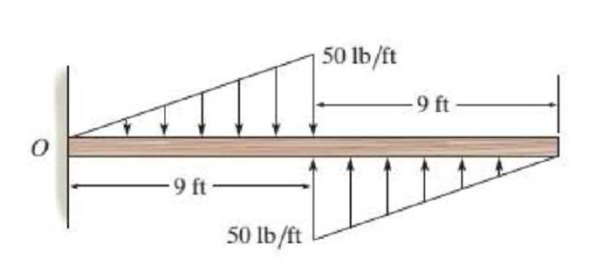
Prob.3-108
Expert Solution & Answer
Want to see the full answer?
Check out a sample textbook solution
Students have asked these similar questions
=
The forces F₁ = 590 lb, F₂ = 380 lb, F3 = 240 lb and F
330 lb. Determine the forces in each member of the truss.
Use positive values to indicate tension and negative values to
indicate compression.
a
a
a
D
b
F₁
A
000
B.
779977
F₂V
H
G
E
F4
b
BY NC SA
2013 Michael Swanbom
Values for dimensions on the figure are given in the following
table. Note the figure may not be to scale.
Variable Value
a
6 ft
b
10.1 ft
The force in member AB is
lb.
The force in member AH is
lb.
The force in member GH is
lb.
The force in member BH is
lb.
The force in member BC is
lb.
The force in member BG is
lb.
The force in member EG is
lb.
The force in member CD is
lb.
The force in member DE is
lb.
The force in member CE is
lb.
The force in member CG is
lb.
Multiple Choice
Circle the best answer to each statement.
1. Which type of surface deviation is controlled by a cy-
lindricity tolerance but not by a circularity tolerance?
A.
B.
C.
Ovality
Taper
Lobing
D. None of the above
2. When verifying a cylindricity tolerance, the inspec-
tion method must be able to collect a set of points and
determine the:
A. Distance between two coaxial cylinders that con-
tain the set of points
B.
Cylinder that circumscribes the set of points
C. Cylinder that inscribes the set of points
D.
Distance between two coaxial circles that contain
the set of points
3. Where Rule #1 applies to a cylindrical regular feature
of size, the tolerance value of a cylindricity tolerance
applied to the feature of size must be
tolerance.
A. Less than
B. Equal to
C. Greater than
D. None of the above
the size
4. Which of the following modifiers may be applied with
a cylindricity tolerance?
A. M
B.
C. ℗
D. Ø
5. Which geometric tolerance can provide an indirect
cylindricity…
The beam AB is attached to the wall in the xz plane by a
fixed support at A. A force of
F = (−129î + 69.0ĵ + 3591) N is applied to the end of
the beam at B. The weight of the beam can be modeled with
a uniform distributed load of intensity w = 85.0 N/m acting in
the negative z direction along its entire length. Find the
support reactions at A.
Z
с
A
b
a
B
F
y
Cc 10
BY NC SA
2016 Eric Davishahl
X
Values for dimensions on the figure are given in the following.
table. Note the figure may not be to scale.
Variable
Value
a
5.60 m
b
5.00 m
C
3.70 m
A
II
=
MA = (
m
2.>
~.>
+
+
k) N
k) N-
Chapter 3 Solutions
Statics and Mechanics of Materials (5th Edition)
Ch. 3.4 - In each case, determine the moment of the force...Ch. 3.4 - In each case, set up the determinant to find the...Ch. 3.4 - Determine the moment of the force about point O....Ch. 3.4 - Determine the moment of the force about point O....Ch. 3.4 - Determine the moment of the force about point O....Ch. 3.4 - Determine the moment of the force about point O....Ch. 3.4 - Determine the moment of the force about point O....Ch. 3.4 - Determine the moment of the force about point O....Ch. 3.4 - Determine the resultant moment produced by the...Ch. 3.4 - Determine the resultant moment produced by the...
Ch. 3.4 - Prob. 9FPCh. 3.4 - Prob. 10FPCh. 3.4 - Determine the moment of force F about point O....Ch. 3.4 - If F1 = {100i 120j + 75k} lb and F2 = {200i +...Ch. 3.4 - Prob. 1PCh. 3.4 - Prove the triple scalar product identity A(B C) =...Ch. 3.4 - Given the three nonzero vectors A, B, and C, show...Ch. 3.4 - Determine the moment about point A of each of the...Ch. 3.4 - Determine the moment about point B of each of the...Ch. 3.4 - Prob. 6PCh. 3.4 - Determine the moment of each of the three forces...Ch. 3.4 - Determine the moment of each of the three forces...Ch. 3.4 - Prob. 9PCh. 3.4 - If FB= 30 lb and FC = 45 lb, determine the...Ch. 3.4 - The cable exerts a force of P = 6 kN at the end of...Ch. 3.4 - The cable exerts a force of P = 6 kN at the end of...Ch. 3.4 - Prob. 13PCh. 3.4 - The 20-N horizontal force acts on the handle of...Ch. 3.4 - Two men exert forces of F = 80 lb and P = 50 lb on...Ch. 3.4 - If the man at B exerts a force of P = 30 lb on the...Ch. 3.4 - Prob. 17PCh. 3.4 - Prob. 18PCh. 3.4 - Prob. 19PCh. 3.4 - The handle of the hammer is subjected to the force...Ch. 3.4 - Prob. 21PCh. 3.4 - Prob. 22PCh. 3.4 - The tower crane is used to hoist the 2-Mg load...Ch. 3.4 - The tower crane is used to hoist a 2-Mg load...Ch. 3.4 - Prob. 25PCh. 3.4 - If the 1500-lb boom AB, the 200-lb cage BCD, and...Ch. 3.4 - Prob. 27PCh. 3.4 - Determine the moment of the force F about point P....Ch. 3.4 - The force F = {400i 100j 700k} lb acts at the...Ch. 3.4 - Prob. 30PCh. 3.4 - Determine the moment of the force F about point P....Ch. 3.4 - Prob. 32PCh. 3.4 - A 20-N horizontal force is applied perpendicular...Ch. 3.4 - A 20-N horizontal force is applied perpendicular...Ch. 3.4 - The pipe assembly is subjected to the 80-N force....Ch. 3.4 - The pipe assembly is subjected to the 80-N force....Ch. 3.4 - A force of F = {6i 2j + lk) kN produces a moment...Ch. 3.4 - The force F = {6i + 8j + l0k} N creates a moment...Ch. 3.5 - In each case, determine the resultant moment of...Ch. 3.5 - In each case, set up the determinant needed to...Ch. 3.5 - Determine the magnitude of the moment of the force...Ch. 3.5 - Determine the magnitude of the moment of the force...Ch. 3.5 - Determine the magnitude of the moment of the 200-N...Ch. 3.5 - Determine the magnitude of the moment of the force...Ch. 3.5 - Prob. 17FPCh. 3.5 - Determine the moment of force F about the x, the...Ch. 3.5 - The lug nut on the wheel of the automobile is to...Ch. 3.5 - Prob. 40PCh. 3.5 - The A-frame is being hoisted into an upright...Ch. 3.5 - Prob. 42PCh. 3.5 - Determine the magnitude of the moment of the force...Ch. 3.5 - Determine the moment of force F about an axis...Ch. 3.5 - Prob. 45PCh. 3.5 - The board is used to hold the end of the cross lug...Ch. 3.5 - The A-frame is being hoisted into an upright...Ch. 3.5 - Prob. 48PCh. 3.5 - Prob. 49PCh. 3.5 - Determine the magnitude of the moment of the force...Ch. 3.5 - Prob. 51PCh. 3.5 - Prob. 52PCh. 3.5 - Determine the moment of the force about the aa...Ch. 3.6 - Determine the resultant couple moment acting on...Ch. 3.6 - Determine the resultant couple moment acting on...Ch. 3.6 - Prob. 21FPCh. 3.6 - Prob. 22FPCh. 3.6 - Prob. 23FPCh. 3.6 - Prob. 24FPCh. 3.6 - A clockwise couple M = 5 N m is resisted by the...Ch. 3.6 - A twist of 4 N m is applied to the handle of the...Ch. 3.6 - If the resultant couple of the three couples...Ch. 3.6 - If F = 125 1b, determine the resultant couple...Ch. 3.6 - Determine the magnitude of F so that the resultant...Ch. 3.6 - Determine the magnitude and coordinate direction...Ch. 3.6 - Prob. 60PCh. 3.6 - Prob. 61PCh. 3.6 - Prob. 62PCh. 3.6 - Prob. 63PCh. 3.6 - Express the moment of the couple acting on the...Ch. 3.6 - If the couple moment acting on the pipe has a...Ch. 3.6 - Prob. 66PCh. 3.6 - Prob. 67PCh. 3.6 - Express the moment of the couple acting on the rod...Ch. 3.6 - Prob. 69PCh. 3.6 - Prob. 70PCh. 3.7 - In each case, determine the x and y components of...Ch. 3.7 - Prob. 25FPCh. 3.7 - Replace the loading by an equivalent resultant...Ch. 3.7 - Prob. 27FPCh. 3.7 - Replace the loading by an equivalent resultant...Ch. 3.7 - Prob. 29FPCh. 3.7 - Prob. 30FPCh. 3.7 - Prob. 71PCh. 3.7 - Prob. 72PCh. 3.7 - Prob. 73PCh. 3.7 - Replace the loading acting on the beam by an...Ch. 3.7 - Replace the loading acting on the beam by an...Ch. 3.7 - Prob. 76PCh. 3.7 - Replace the loading acting on the post by an...Ch. 3.7 - Replace the loading acting on the post by a...Ch. 3.7 - Prob. 79PCh. 3.7 - Prob. 80PCh. 3.7 - Prob. 81PCh. 3.7 - Prob. 82PCh. 3.7 - Prob. 83PCh. 3.7 - Replace the force of F = 80 N acting on the pipe...Ch. 3.7 - Prob. 85PCh. 3.7 - The belt passing over the pulley is subjected to...Ch. 3.8 - In each case, determine the x and y components of...Ch. 3.8 - Prob. 7PPCh. 3.8 - Replace the loading by an equivalent resultant...Ch. 3.8 - Prob. 32FPCh. 3.8 - Prob. 33FPCh. 3.8 - Replace the loading by an equivalent resultant...Ch. 3.8 - Replace the loading by an equivalent single...Ch. 3.8 - Prob. 36FPCh. 3.8 - Prob. 87PCh. 3.8 - Prob. 88PCh. 3.8 - Prob. 89PCh. 3.8 - Prob. 90PCh. 3.8 - Replace the loading by a single resultant force....Ch. 3.8 - Replace the loading by a single resultant force....Ch. 3.8 - Replace the loading by a single resultant force....Ch. 3.8 - Prob. 94PCh. 3.8 - Replace the loading on the frame by a single...Ch. 3.8 - Replace the loading acting on the post by a...Ch. 3.8 - Replace the loading acting on the post by a...Ch. 3.8 - Replace the parallel force system acting on the...Ch. 3.8 - Replace the loading acting on the frame by an...Ch. 3.8 - Replace the loading acting on the frame by an...Ch. 3.8 - If FA = 7 kN and FB = 5 kN, represent the force...Ch. 3.8 - Determine the magnitudes of FA and FB so that the...Ch. 3.8 - Prob. 103PCh. 3.8 - The building slab is subjected to four parallel...Ch. 3.8 - The building slab is subjected to four parallel...Ch. 3.8 - If FA = 40 kN and FB = 35 kN, determine the...Ch. 3.8 - If the resultant force is required to act at the...Ch. 3.9 - Determine the resultant force and specify where it...Ch. 3.9 - Prob. 38FPCh. 3.9 - Determine the resultant force and specify where it...Ch. 3.9 - Prob. 40FPCh. 3.9 - Prob. 41FPCh. 3.9 - Prob. 42FPCh. 3.9 - Replace the loading by an equivalent resultant...Ch. 3.9 - Replace the distributed loading with an equivalent...Ch. 3.9 - Replace the loading by an equivalent resultant...Ch. 3.9 - Currently eighty-five percent of all neck injuries...Ch. 3.9 - Prob. 112PCh. 3.9 - Replace the distributed loading by an equivalent...Ch. 3.9 - Replace the distributed loading by an equivalent...Ch. 3.9 - Prob. 115PCh. 3.9 - Determine the equivalent resultant force and...Ch. 3.9 - Determine the magnitude of the equivalent...Ch. 3 - The boom has a length of 30 ft, a weight of 800...Ch. 3 - Replace the force F having a magnitude of F = 50...Ch. 3 - The hood of the automobile is supported by the...Ch. 3 - Prob. 4RPCh. 3 - Prob. 5RPCh. 3 - Prob. 6RPCh. 3 - The building slab is subjected to four parallel...Ch. 3 - Replace the distributed loading by an equivalent...
Knowledge Booster


Learn more about
Need a deep-dive on the concept behind this application? Look no further. Learn more about this topic, mechanical-engineering and related others by exploring similar questions and additional content below.Similar questions
- need help?arrow_forwardA bent pipe is attached to a wall with brackets as shown. A force of F = 180 lb is applied to the end of the tube with direction indicated by the dimensions in the figure. Determine the support reactions at the brackets B, C, and D. Model these brackets as journal bearings (only force reactions perpendicular to the axis of the tube) and neglect couple moment reactions. Assume the distance between the supports at B and C and the tube bends nearby are negligible such that the support at C is directly above the support at D and the dimension g gives the distance between supports B and C. Enter your answers in Cartesian components. 2013 Michael Swanbom cc 10 BY NC SA g h א B 8° У A C x каж Values for dimensions on the figure are given in the table below. Note the figure may not be to scale. Variable Value a 6.72 in b 11.8 in с 14.8 in d 42.0 in h 26.6 in g 28.0 in → The reaction at B is B = lb. The reaction at C is C = lb. The reaction at D is D = lb. + << + + 2. + + 557 〈んarrow_forwardThe force F1 = 10 kN, F2 = 10 kN, F3 = 10 kN, F4 = 5 KN are acting on the sttructure shown. Determine the forces in the members specified below. Use positive values to indicate tension and negative values to indicate compression. F2 D b F1 F3 C E b F4 b B F a G Values for dimensions on the figure are given in the following table. Note the figure may not be to scale. Variable Value a 3 m b 4 m The force in member BC is KN. The force in member BE is KN. The force in member EF is KN.arrow_forward
- h = The transmission tower is subjected to the forces F₁ 3.6 KN at 50° and F2 = 3.3 kN at = 35°. Determine the forces in members BC, BP, PQ, PC, CD, DP and NP. Use positive values to indicate tension and negative values to indicate compression. 不 кажаж в *а*аж E N M d d IF, c B CENTER LINE S อ K F₂ Kbb cc 10 BY NC SA 2013 Michael Swanbom Values for dimensions on the figure are given in the following table. Note the figure may not be to scale. Variable Value a 1.7 m b 4.9 m с 3 m d 5.2 m h 8.4 m Values for dimensions on the figure are given in the following table. Note the figure may not be to scale. Variable Value a 1.7 m 4.9 m с 3 m d 5.2 m h 8.4 m The force in member BC is KN. The force in member BP is KN. The force in member PQ is KN. The force in member PC is KN. The force in member CD is KN. The force in member DP is KN. The force in member NP is KN.arrow_forwardنصاف Sheet Asteel bar of rectangular cross section with dimension Shown in fig. below. This bar is as Connected toawell. Using welded Join a long the sides als only find the weld size (h). Where: Tall = 35 MN/M² F=213.30 answer/h= 4.04 ☐ Yomm Soomm 100mmarrow_forwardFEAarrow_forward
- FEAarrow_forwardHELP?arrow_forwardTrue and False Indicate if each statement is true or false. T/F 1. Rule #1 protects the function of assembly. T/F 2. One of the fundamental dimensioning rules requires all dimensions apply in the free-state condition for rigid parts. T/F 3. The fundamental dimensioning rules that apply on a drawing must be listed in the general notes. T/F 4. Where Rule #1 applies to a drawing, it limits the form of every feature of size on the drawing. T/F 5. Rule #1 limits the variation between features of size on a part. T/F 6. The designer must specify on the drawing which features of size use Rule #1. T/F T/F T/F 7. Rule #1 applies to nonrigid parts (in the unrestrained state). 8. A GO gage is a fixed-limit gage. 9. Rule #1 requires that the form of an individual regular feature of size is controlled by its limits of sizearrow_forward
arrow_back_ios
SEE MORE QUESTIONS
arrow_forward_ios
Recommended textbooks for you
 Elements Of ElectromagneticsMechanical EngineeringISBN:9780190698614Author:Sadiku, Matthew N. O.Publisher:Oxford University Press
 Mechanics of Materials (10th Edition)Mechanical EngineeringISBN:9780134319650Author:Russell C. HibbelerPublisher:PEARSON
 Thermodynamics: An Engineering ApproachMechanical EngineeringISBN:9781259822674Author:Yunus A. Cengel Dr., Michael A. BolesPublisher:McGraw-Hill Education
 Control Systems EngineeringMechanical EngineeringISBN:9781118170519Author:Norman S. NisePublisher:WILEY
 Mechanics of Materials (MindTap Course List)Mechanical EngineeringISBN:9781337093347Author:Barry J. Goodno, James M. GerePublisher:Cengage Learning
 Engineering Mechanics: StaticsMechanical EngineeringISBN:9781118807330Author:James L. Meriam, L. G. Kraige, J. N. BoltonPublisher:WILEY
Elements Of Electromagnetics
Mechanical Engineering
ISBN:9780190698614
Author:Sadiku, Matthew N. O.
Publisher:Oxford University Press
Mechanics of Materials (10th Edition)
Mechanical Engineering
ISBN:9780134319650
Author:Russell C. Hibbeler
Publisher:PEARSON
Thermodynamics: An Engineering Approach
Mechanical Engineering
ISBN:9781259822674
Author:Yunus A. Cengel Dr., Michael A. Boles
Publisher:McGraw-Hill Education
Control Systems Engineering
Mechanical Engineering
ISBN:9781118170519
Author:Norman S. Nise
Publisher:WILEY
Mechanics of Materials (MindTap Course List)
Mechanical Engineering
ISBN:9781337093347
Author:Barry J. Goodno, James M. Gere
Publisher:Cengage Learning
Engineering Mechanics: Statics
Mechanical Engineering
ISBN:9781118807330
Author:James L. Meriam, L. G. Kraige, J. N. Bolton
Publisher:WILEY
Types Of loads - Engineering Mechanics | Abhishek Explained; Author: Prime Course;https://www.youtube.com/watch?v=4JVoL9wb5yM;License: Standard YouTube License, CC-BY