
Engineering Mechanics: Statics Plus Mastering Engineering with Pearson eText -- Access Card Package (14th Edition) (Hibbeler, The Engineering Mechanics: Statics & Dynamics Series, 14th Edition)
14th Edition
ISBN: 9780134160689
Author: Russell C. Hibbeler
Publisher: PEARSON
expand_more
expand_more
format_list_bulleted
Concept explainers
Videos
Textbook Question
Chapter 3.3, Problem 4P
The bottom one is subjected to a 125-N force at its contact A due to the load on the shaft. Determine the normal reactions NB and NC on the bearing at its contact points B and C for equilibrium.
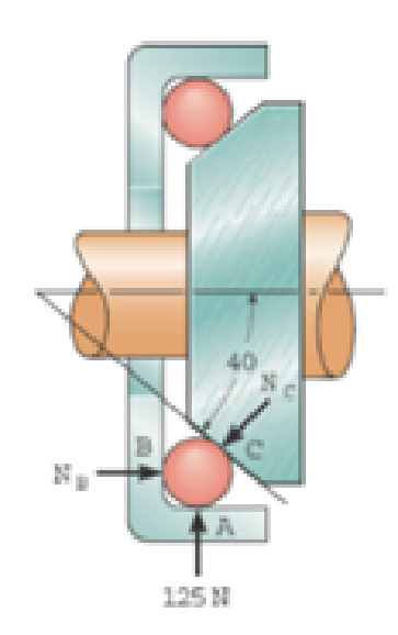
Prob. 3-4
Expert Solution & Answer

Learn your wayIncludes step-by-step video

schedule03:45
Students have asked these similar questions
M16x2 grade 8.8 bolts No. 25 C1-
Q.2. The figure is a cross section of a grade 25 cast-iron pressure vessel. A
total of N, M16x2.0 grade 8.8 bolts are to be used to resist a separating
force of 160 kN. (a) Determine ks, km, and C. (b) Find the number of bolts
required for a load factor of 2 where the bolts may be reused when the joint 19 mm
is taken apart. (c) with the number of bolts obtained in (b), determine the
realized load factor for overload, the yielding factor of safety, and the
separation factor of safety.
19 mm
Problem4.
The thin uniform disk of mass m = 1-kg and radius R = 0.1m spins about the bent shaft OG with
the angular speed w2 = 20 rad/s. At the same time, the shaft rotates about the z-axis with the angular
speed 001 = 10 rad/s. The angle between the bent portion of the shaft and the z-axis is ẞ = 35°. The
mass of the shaft is negligible compared to the mass of the disk.
a. Find the angular momentum of the disk with respect to point G, based on the axis
orientation as shown. Include an MVD in your solution.
b. Find the angular momentum of the disk with respect to point O, based on the axis
orientation as shown. (Note: O is NOT the center of fixed-point rotation.)
c. Find the kinetic energy of the assembly.
z
R
R
002
2R
x
Answer: H = -0.046ĵ-0.040 kg-m²/sec
Ho=-0.146-0.015 kg-m²/sec
T 0.518 N-m
=
Problem 3.
The assembly shown consists of a solid sphere of mass m and the uniform slender rod of the same
mass, both of which are welded to the shaft. The assembly is rotating with angular velocity w at a
particular moment. Find the angular momentum with respect to point O, in terms of the axes
shown.
Answer: Ñ。 = ½mc²wcosßsinßĵ + (}{mr²w + 2mb²w + ½ mc²wcos²ß) k
3
m
r
b
2
C
لا
m
Chapter 3 Solutions
Engineering Mechanics: Statics Plus Mastering Engineering with Pearson eText -- Access Card Package (14th Edition) (Hibbeler, The Engineering Mechanics: Statics & Dynamics Series, 14th Edition)
Ch. 3.3 - In each case, draw a free-body diagram of the ring...Ch. 3.3 - Do not solve.Ch. 3.3 - Determine the force in each supporting cable.Ch. 3.3 - Determine the shortest cable ABC that can be used...Ch. 3.3 - Neglect the size of the pulley.Ch. 3.3 - Determine the unstretched length of the spring.Ch. 3.3 - If the mass of cylinder C is 40 kg, determine the...Ch. 3.3 - Also, find the angle .Ch. 3.3 - Determine the magnitudes of F1 and F2 for...Ch. 3.3 - Determine the magnitude of F1 and its angle for...
Ch. 3.3 - Determine the magnitude and direction of F so...Ch. 3.3 - The bottom one is subjected to a 125-N force at...Ch. 3.3 - If the forces are concurrent at point O, determine...Ch. 3.3 - Determine the tension force in member C and its...Ch. 3.3 - If the tension in AB is 60 lb, determine the...Ch. 3.3 - The cords ABC and BD can each support a maximum...Ch. 3.3 - Determine the maximum force F that can be...Ch. 3.3 - Determine the angle for equilibrium and the force...Ch. 3.3 - Prob. 11PCh. 3.3 - Determine the force in each of the cables AB and...Ch. 3.3 - Prob. 13PCh. 3.3 - The springs are shown in the equilibrium position.Ch. 3.3 - If the block is held in the equilibrium position...Ch. 3.3 - Note that s = 0 when the cylinders are removed.Ch. 3.3 - Prob. 17PCh. 3.3 - determine the stiffness of the spring to hold the...Ch. 3.3 - Take k = 180 N/m.Ch. 3.3 - If the spring has an unstretched length of 2 ft,...Ch. 3.3 - Cord AB is 2 ft long. Take k = 50 lb/ft.Ch. 3.3 - Determine the horizontal force F applied to the...Ch. 3.3 - Determine the displacement d of the cord from the...Ch. 3.3 - Determine the distances x and y for equilibrium if...Ch. 3.3 - Determine the magnitude of F1 and the distance y...Ch. 3.3 - Determine the force in each cord for equilibrium.Ch. 3.3 - Determine the largest mass of pipe that can be...Ch. 3.3 - If each light has a weight of 50 lb. determine the...Ch. 3.3 - Determine the tension developed in each cord...Ch. 3.3 - Determine the maximum mass of the lamp that the...Ch. 3.3 - If x = 2 m determine the force F and the sag s for...Ch. 3.3 - If F = 80 N. determine the sag s and distance x...Ch. 3.3 - Determine the tension in each cord and the angle ...Ch. 3.3 - Determine the largest weight of the lamp that can...Ch. 3.3 - Also, what is the force in cord AB? Hint: use the...Ch. 3.3 - Determine the position x and the tension developed...Ch. 3.3 - Prob. 37PCh. 3.3 - Take F = 300 N and d = 1 m.Ch. 3.3 - If a force of F = 100 N is applied horizontally to...Ch. 3.3 - If the cable can be attached at either points A...Ch. 3.3 - Determine the position x and the tension in the...Ch. 3.3 - The cord is fixed to a pin at A and passes over...Ch. 3.3 - Establish appropriate dimensions and use an...Ch. 3.3 - If the maximum tension that can be supported by...Ch. 3.3 - If the angle between AB and BC is 30, determine...Ch. 3.3 - If the distance BC is 1.5 m, and AB can support a...Ch. 3.4 - Determine the magnitude of forces F1, F2, F3, so...Ch. 3.4 - Determine the tension developed in cables AB, AC,...Ch. 3.4 - Determine the tension developed in cables AB, AC,...Ch. 3.4 - F310. Determine the tension developed in cables...Ch. 3.4 - Determine the tension in these wires.Ch. 3.4 - Determine the force developed in each cable for...Ch. 3.4 - Determine the magnitudes of F1, F2, and F3 for...Ch. 3.4 - If the bucket and its contents have a total weight...Ch. 3.4 - Each spring has on unstretched length of 2 m and a...Ch. 3.4 - Determine the force in each cable needed to...Ch. 3.4 - Determine the tension in the cables in order to...Ch. 3.4 - Determine the maximum mass of the crate so that...Ch. 3.4 - Determine the force in each cable if F = 500 lb.Ch. 3.4 - Determine the greatest force F that can be applied...Ch. 3.4 - Determine the tens on developed in cables AB and...Ch. 3.4 - Also, what is the force developed along strut AD?Ch. 3.4 - Determine the tension developed in each cable for...Ch. 3.4 - Determine the maximum weight of the crate that can...Ch. 3.4 - Prob. 56PCh. 3.4 - If each cord can sustain a maximum tension of 50 N...Ch. 3.4 - which has a mass of 15 kg. Take h = 4 m.Ch. 3.4 - Take h = 3.5 m.Ch. 3.4 - Determine the force in each chain for equilibrium....Ch. 3.4 - Determine the tension in each cable for...Ch. 3.4 - If the maximum force in each rod con not exceed...Ch. 3.4 - Determine the tension developed in each cable for...Ch. 3.4 - If cable AD is tightened by a turnbuckle and...Ch. 3.4 - If cable AD is tightened by a turnbuckle and...Ch. 3.4 - Determine the tension developed in cables AB, AC,...Ch. 3.4 - Determine the maximum weight of the crate so that...Ch. 3.4 - If the bolt exerts a force of 50 lb on the pipe in...Ch. 3.4 - Prob. 2RPCh. 3.4 - Determine the maximum weight of the flowerpot that...Ch. 3.4 - Determine the magnitude of the applied vertical...Ch. 3.4 - Prob. 5RPCh. 3.4 - Determine the magnitudes of F1, F2, and F3 for...Ch. 3.4 - Determine the force in each cable needed to...Ch. 3.4 - If cable AB is subjected to a tension of 700 N,...
Additional Engineering Textbook Solutions
Find more solutions based on key concepts
Determine the bending stress at corners A and B. What is the orientation of the neutral axis?
Mechanics of Materials (10th Edition)
Define each of the following terms: supertype subtype specialization entity cluster completeness constraint enh...
Modern Database Management
What is the purpose of an objects sizing handles?
Starting Out With Visual Basic (8th Edition)
For the circuit shown, use the node-voltage method to find v1, v2, and i1.
How much power is delivered to the c...
Electric Circuits. (11th Edition)
Although it is kind of silly, state legislatures have been known to pass laws that change the value of pi. Supp...
Java: An Introduction to Problem Solving and Programming (8th Edition)
7.13* For a bearing
DE = NUS 5 53’56 ”WT and angles to the right, compute the bearing of PG if angle
DEF 2 88°...
Elementary Surveying: An Introduction To Geomatics (15th Edition)
Knowledge Booster


Learn more about
Need a deep-dive on the concept behind this application? Look no further. Learn more about this topic, mechanical-engineering and related others by exploring similar questions and additional content below.Similar questions
- I have Euler parameters that describe the orientation of N relative to Q, e = -0.7071*n3, e4 = 0.7071. I have Euler parameters that describe the orientation of U relative to N, e = -1/sqrt(3)*n1, e4 = sqrt(2/3). After using euler parameter rule of successive rotations, I get euler parameters that describe the orientation of U relative to Q, e = -0.4082*n1 - 0.4082*n2 - 0.5774*n3. I need euler parameters that describe the orientation of U relative to Q in vector basis of q instead of n. How do I get that?arrow_forwardDescribe at least 4 processes in engineering where control charts are (or should be) appliedarrow_forwardDescribe at least two (2) processes where control charts are (or should be) applied.arrow_forward
- Problem 3: A cube-shaped spacecraft is in a circular Earth orbit. Let N (n,) be inertial and the spacecraft is denoted S (ŝ₁). The spacecraft is described such that ¯½º = J ŝ₁ŝ₁ + J ŝ₂§₂ + J §¸Ŝ3 Location of the spacecraft in the orbit is determined by the orbit-fixed unit vectors ê, that are oriented by the angle (Qt), where is a constant angular rate. 52 €3 3> 2t 55 Λ Из At the instant when Qt = 90°, the spacecraft S is oriented relative to the orbit such that 8₁ = 0° Space-three 1-2-3 angles 0₂ = 60° and ES = $₂ rad/s 0₁ = 135° (a) At this instant, determine the direction cosine matrix that describes the orientation of the spacecraft with respect to the inertial frame N.arrow_forwardThis problem illustrates that the factor of safety for a machine element depends on the particular point selected for analysis. Here you are to compute factors of safety, based upon the distortion-energy theory, for stress elements at A and B of the member shown in the figure. This bar is made of AISI 1006 cold-drawn steel and is loaded by the forces F = 1.100 kN, P = 8.00 kN, and T = 50.00 N-m. Given: Sy = 280 MPa. B -100 mm- 15-mm D. a) Determine the value of the axial stress at point B. b) Determine the value of the shear stress at point B. c) Determine the value of the Von Mises stress at point B. P Farrow_forwardA piston-cylinder device initially contains 0.08 m^3 of nitrogen gas at 130 kPa and 170°C. The nitrogen is expanded to a pressure of 80 kPa via isentropic expansion. Determine the final temperature and the boundary work done by the system during this process.arrow_forward
- A Carnot (ideal) heat pump is to be used to heat a house and maintain it at 22°C in winter. On a day when the average outdoor temperature remains at about 0°C, the house is estimated to lose heat at a rate of 65,000 kJ/h. If the heat pump consumes 6 kW of power while operating, determine: (a) how long the heat pump ran on that day (b) the total heating costs, assuming an average price of 11¢/kWh for electricity (c) the heating cost for the same day if an 85% efficient electric furnace is used instead of a heat pump.arrow_forwardFrom the information in the image, I needed to find the orientation of U relative to Q in vector basis q_hat. I transformed the euler angle/axis representation to euler parameters. Then I got its conjugate in order to get the euler parameter in N frame relative to Q. The problem gave the euler angle/axis representation in Q frame relative to N, so I needed to find the conjugate. Then I used the euler parameter rule of successive rotation to find the final euler parameters that describe the orientation of U relative to Q. However that orientation is in n_hat which is the intermediate frame. How do I get the final result in q_hat?arrow_forwardA proposed method of power generation involves collecting and storing solar energy in large artificial lakes a few meters deep, called solar ponds. Solar energy is absorbed by all parts of the pond, and the water temperature rises everywhere. The top part of the pond, however, loses much of the heat it absorbs to the atmosphere, and as a result, the cool surface water serves as insulation for the bottom part of the pond and helps trap the energy there. Usually, salt is planted at the bottom of the pond to prevent the rise of this hot water to the top. A heat engine that uses an organic fluid, such as alcohol, as the working fluid can be operated between the top and the bottom portions of the pond. If the water temperature is 27°C near the surface and 72°C near the bottom of the pond, determine the maximum thermal efficiency that this power plant can have. Treat the cycle as an ideal heat engine. Would a heat engine operating under these temperature conditions (27°C and 72°C) be…arrow_forward
arrow_back_ios
SEE MORE QUESTIONS
arrow_forward_ios
Recommended textbooks for you
 Elements Of ElectromagneticsMechanical EngineeringISBN:9780190698614Author:Sadiku, Matthew N. O.Publisher:Oxford University Press
 Mechanics of Materials (10th Edition)Mechanical EngineeringISBN:9780134319650Author:Russell C. HibbelerPublisher:PEARSON
 Thermodynamics: An Engineering ApproachMechanical EngineeringISBN:9781259822674Author:Yunus A. Cengel Dr., Michael A. BolesPublisher:McGraw-Hill Education
 Control Systems EngineeringMechanical EngineeringISBN:9781118170519Author:Norman S. NisePublisher:WILEY
 Mechanics of Materials (MindTap Course List)Mechanical EngineeringISBN:9781337093347Author:Barry J. Goodno, James M. GerePublisher:Cengage Learning
 Engineering Mechanics: StaticsMechanical EngineeringISBN:9781118807330Author:James L. Meriam, L. G. Kraige, J. N. BoltonPublisher:WILEY
Elements Of Electromagnetics
Mechanical Engineering
ISBN:9780190698614
Author:Sadiku, Matthew N. O.
Publisher:Oxford University Press
Mechanics of Materials (10th Edition)
Mechanical Engineering
ISBN:9780134319650
Author:Russell C. Hibbeler
Publisher:PEARSON
Thermodynamics: An Engineering Approach
Mechanical Engineering
ISBN:9781259822674
Author:Yunus A. Cengel Dr., Michael A. Boles
Publisher:McGraw-Hill Education
Control Systems Engineering
Mechanical Engineering
ISBN:9781118170519
Author:Norman S. Nise
Publisher:WILEY
Mechanics of Materials (MindTap Course List)
Mechanical Engineering
ISBN:9781337093347
Author:Barry J. Goodno, James M. Gere
Publisher:Cengage Learning
Engineering Mechanics: Statics
Mechanical Engineering
ISBN:9781118807330
Author:James L. Meriam, L. G. Kraige, J. N. Bolton
Publisher:WILEY
Force | Free Body Diagrams | Physics | Don't Memorise; Author: Don't Memorise;https://www.youtube.com/watch?v=4Bwwq1munB0;License: Standard YouTube License, CC-BY