
Videos
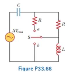
A capacitor, a coil, and two resistors of equal resistance are arranged in an AC circuit as shown in Figure P33.66 (page 1028). An AC source provides an emf of ΔVrms = 20.0 V at a frequency of 60.0 Hz. When the double throw switch S is open as shown in the figure, the rms current is 183 mA. When the switch is closed in position a, the rms current is 298 mA. When the switch is closed in position b, the rms current is 137 mA. Determine the values of (a) R, (b) C, and (c) L. (d) Is more than one set of values possible? Explain.
(a)
The value of resistance.
Answer to Problem 33.66AP
The value of resistance is
Explanation of Solution
Given info: The value of the source emf is
The expression for inductive reactance is,
Here,
The expression for capacitive reactance is,
Here,
The expression for the impedance of the circuit is.
Here,
The expression of the impedance in terms of voltage and current is,
Here,
The figure below depicts the circuit when the switch is in open condition.
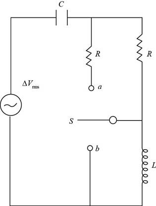
Figure (1)
From figure(1), for the throw switch in open condition:
Substitute
Substitute
For the throw switch at a position:
The two resistances are in parallel.
The expression of the equivalent resistance is.
Substitute
Substitute
Subtract equation (2) from equation (1).
Conclusion:
Therefore, the value of resistance is
(b)
The value of the capacitance.
Answer to Problem 33.66AP
The value of the capacitance is
Explanation of Solution
Given info: The value of the source emf is
The figure below depicts the circuit when switch is at position b.
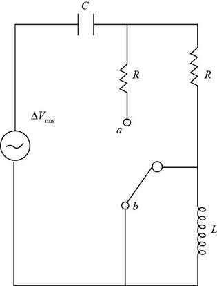
Figure (2)
From figure (2), for the throw switch at b position:
When the switch is at position b the inductor gets short circuited.
Substitute
Rearrange the above expression for value of
Substitute
Substitute
Rearrange the above equation for value of value of
Substitute
Conclusion:
Therefore, the value of the capacitance is
(c)
The value of the inductance.
Answer to Problem 33.66AP
The values of the inductance are
Explanation of Solution
Given info: The value of the source emf is
Substitute
For first value of the inductor,
Substitute
Substitute
Thus, the first value of the inductor is
For second value of the inductor,
Substitute
Substitute  for f in the above expression.
Thus, the second value of the inductor is
Conclusion:
Therefore, the values of the inductance are
(d)
Whether more than one set of value possible.
Answer to Problem 33.66AP
The resistance and capacitance has one set of values, the inductor has in two set of values.
Explanation of Solution
Given info: : The value of the source emf is
From the calculation in part (a),(b) and (c),
The value of resistance is
The value of capacitance is
The values of the inductor are
Hence the resistance and the capacitance has one value while the inductor has two set of value in the circuit.
Conclusion:
Therefore, the resistance and capacitance has one set of values, the inductor has in two set of values.
Want to see more full solutions like this?
Chapter 33 Solutions
Physics for Scientists and Engineers, Technology Update (No access codes included)


- Let's assume that the brightness of a field-emission electron gun is given by β = 4iB π² d²α² a) Assuming a gun brightness of 5x10⁸ A/(cm²sr), if we want to have an electron beam with a semi-convergence angle of 5 milliradian and a probe current of 1 nA, What will be the effective source size? (5 points) b) For the same electron gun, plot the dependence of the probe current on the parameter (dpa) for α = 2, 5, and 10 milliradian, respectively. Hint: use nm as the unit for the electron probe size and display the three plots on the same graph. (10 points)arrow_forwardi need step by step clear answers with the free body diagram clearlyarrow_forwardNo chatgpt pls will upvotearrow_forward
- Review the data in Data Table 1 and examine the standard deviations and 95% Margin of Error calculations from Analysis Questions 3 and 4 for the Acceleration of the 1st Based on this information, explain whether Newton’s Second Law of Motion, Equation 1, was verified for your 1st Angle. Equation: SF=ma Please help with explaining the information I collected from a lab and how it relates to the equation and Newton's Second Law. This will help with additional tables in the lab. Thanks!arrow_forwardPlease solve and answer the problem step by step with explanations along side each step stating what's been done correctly please. Thank you!! ( preferably type out everything)arrow_forwardAnswer thisarrow_forward
- No chatgpt pls will upvotearrow_forwardNo chatgpt pls will upvote instantarrow_forwardKirchoff's Laws. A circuit contains 3 known resistors, 2 known batteries, and 3 unknown currents as shown. Assume the current flows through the circuit as shown (this is our initial guess, the actual currents may be reverse). Use the sign convention that a potential drop is negative and a potential gain is positive. E₂ = 8V R₁₁ = 50 R₂ = 80 b с w 11 www 12 13 E₁ = 6V R3 = 20 a) Apply Kirchoff's Loop Rule around loop abefa in the clockwise direction starting at point a. (2 pt). b) Apply Kirchoff's Loop Rule around loop bcdeb in the clockwise direction starting at point b. (2 pt). c) Apply Kirchoff's Junction Rule at junction b (1 pt). d) Solve the above 3 equations for the unknown currents I1, 12, and 13 and specify the direction of the current around each loop. (5 pts) I1 = A 12 = A 13 = A Direction of current around loop abef Direction of current around loop bcde (CW or CCW) (CW or CCW)arrow_forward
- No chatgpt pls will upvotearrow_forward4.) The diagram shows the electric field lines of a positively charged conducting sphere of radius R and charge Q. A B Points A and B are located on the same field line. A proton is placed at A and released from rest. The magnitude of the work done by the electric field in moving the proton from A to B is 1.7×10⁻¹⁶ J. Point A is at a distance of 5.0×10⁻²m from the centre of the sphere. Point B is at a distance of 1.0×10⁻¹ m from the centre of the sphere. (a) Explain why the electric potential decreases from A to B. [2] (b) Draw, on the axes, the variation of electric potential V with distance r from the centre of the sphere. R [2] (c(i)) Calculate the electric potential difference between points A and B. [1] (c(ii)) Determine the charge Q of the sphere. [2] (d) The concept of potential is also used in the context of gravitational fields. Suggest why scientists developed a common terminology to describe different types of fields. [1]arrow_forward3.) The graph shows how current I varies with potential difference V across a component X. 904 80- 70- 60- 50- I/MA 40- 30- 20- 10- 0+ 0 0.5 1.0 1.5 2.0 2.5 3.0 3.5 4.0 4.5 5.0 VIV Component X and a cell of negligible internal resistance are placed in a circuit. A variable resistor R is connected in series with component X. The ammeter reads 20mA. 4.0V 4.0V Component X and the cell are now placed in a potential divider circuit. (a) Outline why component X is considered non-ohmic. [1] (b(i)) Determine the resistance of the variable resistor. [3] (b(ii)) Calculate the power dissipated in the circuit. [1] (c(i)) State the range of current that the ammeter can measure as the slider S of the potential divider is moved from Q to P. [1] (c(ii)) Describe, by reference to your answer for (c)(i), the advantage of the potential divider arrangement over the arrangement in (b).arrow_forward
 Physics for Scientists and Engineers, Technology ...PhysicsISBN:9781305116399Author:Raymond A. Serway, John W. JewettPublisher:Cengage Learning
 Physics for Scientists and Engineers: Foundations...PhysicsISBN:9781133939146Author:Katz, Debora M.Publisher:Cengage Learning
 Physics for Scientists and EngineersPhysicsISBN:9781337553278Author:Raymond A. Serway, John W. JewettPublisher:Cengage Learning
 Physics for Scientists and Engineers with Modern ...PhysicsISBN:9781337553292Author:Raymond A. Serway, John W. JewettPublisher:Cengage Learning
 College PhysicsPhysicsISBN:9781305952300Author:Raymond A. Serway, Chris VuillePublisher:Cengage Learning