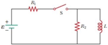
At t = 0, the open switch in Figure P31.46 is thrown closed. We wish to find a symbolic expression for the current in the inductor for time t > 0. Let this current be called i and choose it to be downward in the inductor in Figure P31.46. Identify i1 as the current to the right through R1 and i2 as the current downward through R2. (a) Use Kirchhoff’s junction rule to find a relation among the three currents. (b) Use Kirchhoff’s loop rule around the left loop to find another relationship. (c) Use Kirchhoff’s loop rule around the outer loop to find a third relationship. (d) Eliminate i1 and i2 among the three equations to find an equation involving only the current i. (e) Compare the equation in part (d) with Equation 31.6 in the text. Use this comparison to rewrite Equation 31.7 in the text for the situation in this problem and show that
where R′ = R1R2/(R1 + R2).
Figure P31.46

(a)
Answer to Problem 32.70AP
Explanation of Solution
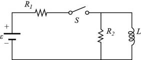
Given info: The figure that shows the given circuit is shown below.

Figure (I)
According to Kirchhoff’s junction rule, the total incoming currents are equal to the total outgoing currents at a junction.
From the circuit diagram equating the incoming currents to the outgoing current,
Here,
Conclusion:
Therefore, the relation among three currents by Kirchhoff’s junction rule are
(b)
Answer to Problem 32.70AP
Explanation of Solution
Given info: The figure that shows the given circuit is shown in figure (I).
According to Kirchhoff’s loop rule, the sum of all the voltage across all the elements in a loop must be zero.
From the circuit diagram equating the voltage across the elements in the left loop is equal to zero.
Here,
Conclusion:
Therefore, the relationship between the given variables around the left loop by Kirchhoff’s loop rule is
(c)
Answer to Problem 32.70AP
Explanation of Solution
Given info: The figure that shows the given circuit is shown in figure (I).
According to Kirchhoff’s loop rule, the sum of all the voltage across all the elements in a loop must be zero.
From the circuit diagram equating the voltage across the elements in the outer loop is equal to zero.
Conclusion:
Therefore, the relationship between the given variables around the outer loop by Kirchhoff’s loop rule is
(d)
Answer to Problem 32.70AP
Explanation of Solution
Given info: The figure that shows the given circuit is shown in figure (I).
From equation (1), the expression for the
Substitute
From equation (2), the expression for the
Substitute
Equate equation (3) and equation (4) for
Further solve the above equation,
Assume
Substitute
Thus, the require equation in term of current
Conclusion:
Therefore, the equation that involve only current
(e)
Answer to Problem 32.70AP
Explanation of Solution
From the textbook the equation
From the part (d), the equation is given as,
Since both the equation shown above are same therefore their solution are also same.
The solution of the equation
Similarly rewrite the equation
Substitute
Conclusion:
Therefore, the equation
Want to see more full solutions like this?
Chapter 32 Solutions
PHYSICS 1250 PACKAGE >CI<
- Show that Equation 32.28 in the text Ls Kirchhoffs loop rule as applied to the circuit in Figure P32.56 with the switch thrown to position b.arrow_forwardA long solenoid with 10 turns per centimeter is placed inside a copper ring such that both objects hove the same central axis. The radius of the ring is 10.0 cm. and the radius of the solenoid is 5.0 cm. (a) What is the emf induced in the ring when the current 2 through the solenoid is 5.0 A and changing at a rate of 100 A/s? (b) What is the emf induced in the ring when 1=2.0A and. dI/dt=100A/s ? (c) What is the electric field inside the ring for these two cases? id: Suppose the ring is moved so that its central axis and the central axis of the solenoid are still parallel but no longer coincide. (You should assume that the solenoid is still inside die ring.) New what is the emf induced in the ring? (el Can you calculate the electric field in die ring as you did in part (c)?arrow_forwardConsider the circuit in Figure P32.18, taking = 6.00 V, L = 8.00 mH, and R = 4.00 . (a) What is the inductive time constant of the circuit? (b) Calculate the current in the circuit 250 s after the switch is closed. (c) What is the value of the final steady-state current? (d) After what time interval does the current reach 80.0% of its maximum value?arrow_forward
- A coil with a self-inductance of 3.0 H and a resistance of 100 2 carries a steady current of 2.0 A. (a) What is the energy stored in the magnetic field of the coil? (b) What is the energy per second dissipated in the resistance of the coil?arrow_forwardA solenoid with 4 x 10⁷turns/m has an iron core placed in it whose magnetic susceptibility is 4.0 x 10³. (a) If a cent of 2.0 A flows through the solenoid, what is the magnetic field in the iron core? (b) What is the effective surface current formed by the aligned atomic current loops in the iron core? (c) What is the self-inductance of the filled solenoid?arrow_forwardA long, cylindrical solenoid with 100 turns per centimeter has a radius of 1.5 cm. (a) Neglecting end effects, that is the self-inductance per unit length of the solenoid? (b) If the current through the solenoid changes at the rate 5.0 AJs, what is the emf induced per unit length?arrow_forward
- A thin wire = 30.0 cm long is held parallel to and d = 80.0 cm above a long, thin wire carrying I = 200 A and fixed in position (Fig. P30.47). The 30.0-cm wire is released at the instant t = 0 and falls, remaining parallel to the current-carrying wire as it falls. Assume the falling wire accelerates at 9.80 m/s2. (a) Derive an equation for the emf induced in it as a function of time. (b) What is the minimum value of the emf? (c) What is the maximum value? (d) What is the induced emf 0.300 s after the wire is released? Figure P30.47arrow_forwardDesign a current loop that, when rotated in a uniform magnetic field of strength 0.10 T, will produce an emf =0 sin t. where 0=110V and 0=110V .arrow_forwardThe switch in the figure has been in position 1 for a long time. It is changed to position 2 at t = 0s. What is the maximum current through the inductor? What is the first time at which the current is maximum? Express your answer to two significant figures and include the appropriate units.arrow_forward
- An infinitely long and thin wire carrying 10 A current is places on the Z-axis away from a triangular loop. The triangle is in the YZ-plane with its vertices at (0, 1, 0), (0, 2, 0) and (0, 1, 2). 1 m a) Find the mutual inductance between the wire and the triangular loop yarrow_forwardConsider the circuit shown in the figure below, where L = 5.05 mH and R₂ = 440 02. The switch S can be positioned at either a or b. S 000 b 404 R₁ 24.0 V L a R₂ (a) When the switch is at position a, the time constant is 15.4 us. What is R₂ (in k)? 1 ΚΩ (b) What is the current in the inductor at the instant the switch is thrown to position b? mA earrow_forwardI just need parts A, E, and F. Thank you! A 10.0 μF capacitor is charged to 175 μC and then connected across the ends of a 6.00 mH inductor. (A) Find the maximum current in the inductor. Express your answer with the appropriate units. (E) Find the maximum energy stored in the inductor. Express your answer with the appropriate units. (F) At the instant the energy stored in the inductor is maximum, what is the current in the circuit? Express your answer with the appropriate units.arrow_forward
 Principles of Physics: A Calculus-Based TextPhysicsISBN:9781133104261Author:Raymond A. Serway, John W. JewettPublisher:Cengage Learning
 Physics for Scientists and EngineersPhysicsISBN:9781337553278Author:Raymond A. Serway, John W. JewettPublisher:Cengage Learning
 Physics for Scientists and Engineers with Modern ...PhysicsISBN:9781337553292Author:Raymond A. Serway, John W. JewettPublisher:Cengage Learning
 Physics for Scientists and Engineers, Technology ...PhysicsISBN:9781305116399Author:Raymond A. Serway, John W. JewettPublisher:Cengage Learning
 Physics for Scientists and Engineers: Foundations...PhysicsISBN:9781133939146Author:Katz, Debora M.Publisher:Cengage Learning


