
Videos
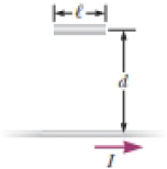
A thin wire ℓ = 30.0 cm long is held parallel to and d = 80.0 cm above a long, thin wire carrying I = 200 A and fixed in position (Fig. P30.47). The 30.0-cm wire is released at the instant t = 0 and falls, remaining parallel to the current-carrying wire as it falls. Assume the falling wire accelerates at 9.80 m/s2. (a) Derive an equation for the emf induced in it as a function of time. (b) What is the minimum value of the emf? (c) What is the maximum value? (d) What is the induced emf 0.300 s after the wire is released?
Figure P30.47
(a)
Answer to Problem 31.78AP
Explanation of Solution
Given info: Length of wire is
The speed of the wire according to Newton’s law of motion can be given as,
Here,
Substitute
The distance covered by the wire can be given as,
Here,
Substitute
The total distance covered by wire can be given as,
Here,
Substitute
The magnetic field at a distance
Here,
The emf induced in the wire can be given as,
Here,
Substitute
Substitute
Conclusion:
Therefore, the equation for emf induced in the wire as function of time is
(b)
Answer to Problem 31.78AP
Explanation of Solution
Given info: Length of wire is
The expression for emf can be given as in equation (1),
At
Conclusion:
Therefore, the minimum value of emf is
(c)
Answer to Problem 31.78AP
Explanation of Solution
Given info: Length of wire is
The expression for emf can be given as in equation (1),
From the above equation, at
Conclusion:
Therefore, the minimum value of emf is
(d)
Answer to Problem 31.78AP
Explanation of Solution
Given info: Length of wire is
The expression for emf can be given as in equation (1),
Substitute
Conclusion:
Therefore, the induced emf
Want to see more full solutions like this?
Chapter 31 Solutions
Physics for Scientists and Engineers, Technology Update (No access codes included)


- 7. A race car accelerates from rest to 55 m s-1 in 5.0 seconds. The acceleration of the car Is m s-² 8. An object's speed increases uniformly from 10.5 km per hour to 99.8 km per hour in 2.41 seconds. Calculate the acceleration in m s-2 and express your answer to three significant figures. 9. The acceleration-time graph of a car is shown below. The initial speed of the car is 5.0 m s-1. # Acceleration (ms) 12 8.0- 4.0- 2.0 4.0 6.0 Time (s) Calculate the velocity of the car at t = 4.0 s. 3arrow_forwardNo chatgpt pls will upvotearrow_forwardNo chatgpt pls will upvotearrow_forward
- Problem Seven. A football receiver running straight downfield at 5.60 m/s is 11.5 m in front of the quarterback when a pass is thrown downfield at an angle of 35.0° horizon. above the 8.) If the receiver never changes speed and the ball is caught at the same height from which it was thrown, find the distance between the quarterback and the receiver when the catch is made. (A) 21.3 (B) 17.8 (C) 18.8 (D) 19.9 (E) 67.5arrow_forwardPlease solve and answer the question correctly please. Thank you!!arrow_forwardPlease solve and answer the question correctly please. Thank you!!arrow_forward
- Please view both photos, and answer the question correctly please. Thank you!!arrow_forwardA thrown brick hits a window, but doesn't break it. Instead it reverses direction and ends down on the ground below the window. Since the brick didn't break the glass, we know: О The force of the brick on the glass > the force of the glass on the brick. О The force of the brick on the glass the force of the glass on the brick. = О The force of the brick on the glass < the force of the glass on the brick. О The brick didn't slow down as it broke the glass.arrow_forwardAlexandra (wearing rubber boots for traction) is attempting to drag her 32.6-kg Golden Retriever across the smooth ice by applying a horizontal force. What force must she apply to move the dog with a constant speed of 0.950 m/s? ☐ 31.0 lb. ☐ 319 kg. ○ Zero. 32.6 kg.arrow_forward
- The figure shows a graph of the acceleration of an object as a function of the net force acting on it. The mass of this object, in grams, is closest to 11 a(m/s²) 8.0+ 6.0- 4.0- 2.0- 0+ F(N) 0.00 0.50 1.00 ☐ 130 ○ 8000 ☐ 89arrow_forwardValues that are within standard deviations represent measurements that are considered to be near the true value. Review the data from the lab and determine whether your data is within standard deviations. Report, using numerical values, whether your data for each angle is within standard deviations. An acceptable margin of error typically falls between 4% and 8% at the 95% confidence level. Review your data for each angle to determine whether the margin of error is within an acceptable range. Report with numerical values, whether your data for each angle is within an acceptable margin of error. Can you help explain what my data means in terms of the standard deviation and the ME? Thanks!arrow_forwardA sinusoidal wave is propagating along a stretched string that lies along the x-axis. The displacement of the string as a function of time is graphed in (Figure 1) for particles at x = 0 and at x = 0.0900 m. You are told that the two points x = 0 and x = 0.0900 m are within one wavelength of each other. If the wave is moving in the +x-direction, determine the wavelength. If instead the wave is moving in the -x-direction, determine the wavelength. Please show all stepsarrow_forward
 Physics for Scientists and Engineers: Foundations...PhysicsISBN:9781133939146Author:Katz, Debora M.Publisher:Cengage Learning
 Principles of Physics: A Calculus-Based TextPhysicsISBN:9781133104261Author:Raymond A. Serway, John W. JewettPublisher:Cengage Learning
 Physics for Scientists and EngineersPhysicsISBN:9781337553278Author:Raymond A. Serway, John W. JewettPublisher:Cengage Learning
 Physics for Scientists and Engineers with Modern ...PhysicsISBN:9781337553292Author:Raymond A. Serway, John W. JewettPublisher:Cengage Learning
 Glencoe Physics: Principles and Problems, Student...PhysicsISBN:9780078807213Author:Paul W. ZitzewitzPublisher:Glencoe/McGraw-Hill