Transcranial magnetic stimulation (TMS) is a noninvasive technique used to stimulate tedious of the human brain (Figure P31.3). In TMS, a small coil is placed on the scalp and a brief burst of current in the coil produces a rapidly changing magnetic field inside the brain. The induced emf can stimulate neuronal activity. (a) One such device generates an upward magnetic Held within the brain that rises from zero to 1.50 T in 120 ms. Determine the induced emf around a horizontal circle of tissue of radius 1.60 mm. (b) What If? The field next changes to 0.500 T downward in 80.0 ms. How does the emf induced in this process compare with that in part (a)? Figure P31.3 Problems 3 and 51. The magnetic coil of a Neurostar TMS apparatus is held near the head of a patient.
Transcranial magnetic stimulation (TMS) is a noninvasive technique used to stimulate tedious of the human brain (Figure P31.3). In TMS, a small coil is placed on the scalp and a brief burst of current in the coil produces a rapidly changing magnetic field inside the brain. The induced emf can stimulate neuronal activity. (a) One such device generates an upward magnetic Held within the brain that rises from zero to 1.50 T in 120 ms. Determine the induced emf around a horizontal circle of tissue of radius 1.60 mm. (b) What If? The field next changes to 0.500 T downward in 80.0 ms. How does the emf induced in this process compare with that in part (a)? Figure P31.3 Problems 3 and 51. The magnetic coil of a Neurostar TMS apparatus is held near the head of a patient.
Solution Summary: The author determines the induced emf around a horizontal circle of tissue.
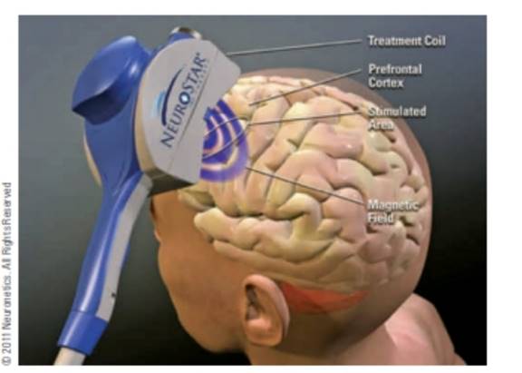
Transcranial magnetic stimulation (TMS) is a noninvasive technique used to stimulate tedious of the human brain (Figure P31.3). In TMS, a small coil is placed on the scalp and a brief burst of current in the coil produces a rapidly changing magnetic field inside the brain. The induced emf can stimulate neuronal activity. (a) One such device generates an upward magnetic Held within the brain that rises from zero to 1.50 T in 120 ms. Determine the induced emf around a horizontal circle of tissue of radius 1.60 mm. (b) What If? The field next changes to 0.500 T downward in 80.0 ms. How does the emf induced in this process compare with that in part (a)?
Figure P31.3 Problems 3 and 51. The magnetic coil of a Neurostar TMS apparatus is held near the head of a patient.
4.) The diagram shows the electric field lines of a positively charged conducting sphere of
radius R and charge Q.
A
B
Points A and B are located on the same field line.
A proton is placed at A and released from rest. The magnitude of the work done by the electric field in
moving the proton from A to B is 1.7×10⁻¹⁶ J. Point A is at a distance of 5.0×10⁻²m from the centre of
the sphere. Point B is at a distance of 1.0×10⁻¹ m from the centre of the sphere.
(a) Explain why the electric potential decreases from A to B. [2]
(b) Draw, on the axes, the variation of electric potential V with distance r from the centre of the
sphere.
R
[2]
(c(i)) Calculate the electric potential difference between points A and B. [1]
(c(ii)) Determine the charge Q of the sphere. [2]
(d) The concept of potential is also used in the context of gravitational fields. Suggest why scientists
developed a common terminology to describe different types of fields. [1]
3.) The graph shows how current I varies with potential difference V across a component X.
904
80-
70-
60-
50-
I/MA
40-
30-
20-
10-
0+
0
0.5
1.0 1.5 2.0 2.5 3.0 3.5 4.0 4.5 5.0
VIV
Component X and a cell of negligible internal resistance are placed in a circuit.
A variable resistor R is connected in series with component X. The ammeter reads 20mA.
4.0V
4.0V
Component X and the cell are now placed in a potential divider circuit.
(a) Outline why component X is considered non-ohmic. [1]
(b(i)) Determine the resistance of the variable resistor. [3]
(b(ii)) Calculate the power dissipated in the circuit. [1]
(c(i)) State the range of current that the ammeter can measure as the slider S of the potential divider
is moved from Q to P. [1]
(c(ii)) Describe, by reference to your answer for (c)(i), the advantage of the potential divider
arrangement over the arrangement in (b).
1.) Two long parallel current-carrying wires P and Q are separated by 0.10 m. The current in wire P is 5.0 A.
The magnetic force on a length of 0.50 m of wire P due to the current in wire Q is 2.0 × 10-s N.
(a) State and explain the magnitude of the force on a length of 0.50 m of wire Q due to the current in P. [2]
(b) Calculate the current in wire Q. [2]
(c) Another current-carrying wire R is placed parallel to wires P and Q and halfway between them as shown.
wire P
wire R
wire Q
0.05 m
0.05 m
The net magnetic force on wire Q is now zero.
(c.i) State the direction of the current in R, relative to the current in P.[1]
(c.ii) Deduce the current in R. [2]
Chapter 31 Solutions
Physics for Scientists and Engineers, Technology Update (No access codes included)
Need a deep-dive on the concept behind this application? Look no further. Learn more about this topic, physics and related others by exploring similar questions and additional content below.
What is Electromagnetic Induction? | Faraday's Laws and Lenz Law | iKen | iKen Edu | iKen App; Author: Iken Edu;https://www.youtube.com/watch?v=3HyORmBip-w;License: Standard YouTube License, CC-BY


 Physics for Scientists and Engineers, Technology ...PhysicsISBN:9781305116399Author:Raymond A. Serway, John W. JewettPublisher:Cengage Learning
 Principles of Physics: A Calculus-Based TextPhysicsISBN:9781133104261Author:Raymond A. Serway, John W. JewettPublisher:Cengage Learning
 College PhysicsPhysicsISBN:9781285737027Author:Raymond A. Serway, Chris VuillePublisher:Cengage Learning
 College PhysicsPhysicsISBN:9781305952300Author:Raymond A. Serway, Chris VuillePublisher:Cengage Learning
 Glencoe Physics: Principles and Problems, Student...PhysicsISBN:9780078807213Author:Paul W. ZitzewitzPublisher:Glencoe/McGraw-Hill
 College PhysicsPhysicsISBN:9781938168000Author:Paul Peter Urone, Roger HinrichsPublisher:OpenStax College