
Concept explainers
(a)
The current in inductor.
(a)
Answer to Problem 15P
Explanation of Solution
Given info: value of resistance
Explanation:
Diagram for the circuit connected with a battery, inductor is given below.
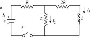
Figure (1)
Formula to calculate current in a loop as per Kirchhoff law is,
Here,
Write the expression for net voltage in loop 1,
Write the expression to calculate net voltage in loop 2,
Here,
Substitute
Substitute
Arrange the terms of above equation to simplify for integration.
On integrate,
Let
Differentiate above equation.
Substitute
Substitute
Apply boundary condition,
Substitute
Substitute
Further solve the above expression.
Substitute
Thus, the current in inductor in the terms of time is
Conclusion:
Therefore, current in inductor in the terms of time is
(b)
The current in the switch as a function of time.
(b)
Answer to Problem 15P
Explanation of Solution
From equation (7), the formula to calculate current in inductor is,
From equation (4), the formula to calculate current in switch is,
Substitute
Substitute
Thus, the current in switch is
Conclusion:
Therefore, the current in switch is
Want to see more full solutions like this?
Chapter 31 Solutions
Physics for Scientists and Engineers
- Show that Equation 32.28 in the text Ls Kirchhoffs loop rule as applied to the circuit in Figure P32.56 with the switch thrown to position b.arrow_forwardConsider the circuit in Figure P32.18, taking = 6.00 V, L = 8.00 mH, and R = 4.00 . (a) What is the inductive time constant of the circuit? (b) Calculate the current in the circuit 250 s after the switch is closed. (c) What is the value of the final steady-state current? (d) After what time interval does the current reach 80.0% of its maximum value?arrow_forwardA coil with a self-inductance of 3.0 H and a resistance of 100 2 carries a steady current of 2.0 A. (a) What is the energy stored in the magnetic field of the coil? (b) What is the energy per second dissipated in the resistance of the coil?arrow_forward
- In the circuit shown in (Figure 1), E = 56.0 V, R₁ = 36.0 , R₂ = 22.0 N, and L = 0.290 H. Figure a www R₁ www. vooo R₂ C L + d 1 of 1 b Part A Switch S is closed. At some time t afterward the current in the inductor is increasing at a rate of di/dt = 50.0 A/s. At this instant, what is the current 2₁ through R₁? Express your answer in amperes. IVE ΑΣΦ ? i₁ = A Submit Request Answer Part B Switch S is closed. At some time t afterward the current in the inductor is increasing at a rate of di/dt = 50.0 A/s. At this instant, what is the current 22 through R2? Express your answer in amperes. IVE ΑΣΦ ? 22 = Submit Request Answer Aarrow_forwardAfter being closed for a long time, the switch S in the circuit shown in the figure below is thrown open at t = 0. In the circuit, & = 24.0 V, RA = 4.40 kQ, RB = 7.20 kn, and L = 684 mH. RA S RB m b L (a) What is the emf across the inductor immediately after the switch is opened? 63.8 v (b) When does the current in the resistor RB have a magnitude of 1.00 mA? Sarrow_forwardYou know that the resistance R is 39.5 N and that the inductor has a nonzero resistance R, in its windings. Switch S, is closed at time t = 0. Your data logger shows the following voltages across the inductor as a function of time, with t = 0 being the 1 instant the switch was thrown closed. t( us) Δν, (V) t(µs) AV, (V) t(us) Av, (V) 48.0 1.60 7.23 3.10 4.72 0.100 41.1 1.70 6.80 3.20 4.69 0.200 35.3 1.80 6.44 3.30 4.66 0.300 30.4 1.90 6.13 3.40 4.64 0.400 26.3 2.00 5.88 3.50 4.62 0.500 22.8 2.10 5.66 3.60 4.60 0.600 19.9 2.20 5.48 3.70 4.59 0.700 17.4 2.30 5.33 3.80 4.58 0.800 15.4 2.40 5.20 3.90 4.57 0.900 13.7 2.50 5.09 4.00 4.56 1.00 12.2 2.60 5.00 4.10 4.55 1.10 11.0 2.70 4.92 4.20 4.55 1.20 9.95 2.80 4.86 4.30 4.54 1.30 9.09 2.90 4.80 4.40 4.54 1.40 8.36 3.00 4.76 4.50 4.54 1.50 7.75 Using these data, discuss this situation in your group and determine the emf of the battery, the resistance R, in the windings of the inductor, and the inductance L. (a) the emf of the battery (in V)…arrow_forward
- Consider the circuit shown in the figure below where L = 5.10 mH and R₂ = 410 N. L voo 24.0 V + a S ob R₁ R₂ (a) When the switch is in position a, for what value of R₁ will the circuit have a time constant of 14.9 µs? ΚΩ (b) What is the current in the inductor at the instant the switch is thrown to position b? mAarrow_forwardConsider the circuit shown in the figure below, where L = 5.05 mH and R₂ = 440 02. The switch S can be positioned at either a or b. S 000 b 404 R₁ 24.0 V L a R₂ (a) When the switch is at position a, the time constant is 15.4 us. What is R₂ (in k)? 1 ΚΩ (b) What is the current in the inductor at the instant the switch is thrown to position b? mA earrow_forwardIn the figure ɛ = 10.0 V, R = 4.00 0, and R2 = 1.00 N. The inductor has an internal resistance of r = 1.00 N. What is the power delivered by the battery as soon as the switch is closed? Give your answer in W. Şekildeki devrede ɛ = 10.0 V, R1 = 4.00 n, ve R2 = 1.00 n olarak verilmişlerdir. Solenoidin iç direnci r = 1.00 N olarak verilmiştir. Anahtar kapatılır kapatılmaz bataryanın devreye verdiği güç W cinsinden nedir? R E- R2 L. Yanıtınızarrow_forward
- A battery of emf 30.0 V is connected to a switch, an inductor of inductance ? = 0.600 ? and two resistors, R1 = 10.0 and R2 = 6.00. The switch is initially open. A. What are the values of currents i1, i2, i3 just after the switch is closed? (Just give an answer) i1= i2 = i3 = B.)Which point, a or b, is at higher potential or are they at the same potential, just after switch S is closed? (Just give an answer) C. What is the value of current i1 through the battery a long time after the switch is closed? Show your work and briefly explain your logicarrow_forwardAn electromagnet can be modeled as an inductor in series with a resistor. Consider a large electromagnet of inductance L = 15.0 H and resistance R = 2.50 2 connected to a 18.0-V battery and switch as in the figure shown below. After the switch is closed, find the following. S + I R www L (a) the maximum current carried by the electromagnet A (b) the time constant of the circuit S (c) the time it takes the current to reach 95.0% of its maximum value Sarrow_forwardA charged capacitor (C= 1μF) is connected in a single loop circuit with an inductor (L= 3mH). ▾ Part A At some time after the switch is closed, the charge on the capacitor is q=2.3µC. At that moment, determine the magnitude of the rate of change of the current. V—| ΑΣΦ + d C ? Amps/s Submit Request Answer ++++++ с Lellearrow_forward
- Principles of Physics: A Calculus-Based TextPhysicsISBN:9781133104261Author:Raymond A. Serway, John W. JewettPublisher:Cengage LearningPhysics for Scientists and Engineers with Modern ...PhysicsISBN:9781337553292Author:Raymond A. Serway, John W. JewettPublisher:Cengage LearningPhysics for Scientists and EngineersPhysicsISBN:9781337553278Author:Raymond A. Serway, John W. JewettPublisher:Cengage Learning
- Physics for Scientists and Engineers: Foundations...PhysicsISBN:9781133939146Author:Katz, Debora M.Publisher:Cengage LearningPhysics for Scientists and Engineers, Technology ...PhysicsISBN:9781305116399Author:Raymond A. Serway, John W. JewettPublisher:Cengage Learning